瑞 鼎 科 技 股 份 有 限 公 司
Raydium Semiconductor Corporation
RM68042 Data Sheet
Single Chip Driver with 262K color
for 320RGBx480 a-Si TFT LCD
Revision:0.6
Date:Apr. 16, 2010
�
RM68041 Data Sheet
Rev:0.6
Revision History
Version No.
Date
Page
Description
V06.0
2010/04/16
Draft
�
RM68041 Data Sheet
Rev:0.6
Table of Contents
Revision History ........................................................................................................................................... 2
1. General Description .................................................................................................................................. 1
2. Features..................................................................................................................................................... 1
3. Block Diagram .......................................................................................................................................... 3
4. Pin Description.......................................................................................................................................... 4
5. Pad Arrangement and Coordination.......................................................................................................... 8
6. Block Function Description .................................................................................................................... 18
7. Function Description............................................................................................................................... 20
7.1. Display Bus Interface (DBI) ........................................................................................................ 20
7.1.1. Write Cycle ....................................................................................................................... 21
7.1.2. Read Cycle ........................................................................................................................ 22
7.2. Serial Interface (Type C) .............................................................................................................. 24
7.2.1. Write Cycle and Sequence ................................................................................................ 24
7.2.2. Read Cycle and Sequence................................................................................................. 26
7.2.3. Break and Pause Sequences.............................................................................................. 29
7.3. Display Pixel Interface (DPI)....................................................................................................... 30
8. Command................................................................................................................................................ 35
8.1. Command List ............................................................................................................................. 35
8.2. Command Description................................................................................................................. 38
8.2.1. NOP (00h) ......................................................................................................................... 38
8.2.2. Soft_reset (01h)................................................................................................................. 39
8.2.3. Get_power_mode (0Ah) ................................................................................................... 41
8.2.4. Get_address_mode (0Bh).................................................................................................. 43
8.2.5. Get_pixel_format (0Ch).................................................................................................... 45
8.2.6. Get_display_mode (0Dh).................................................................................................. 47
8.2.7. Get_signal_mode (0Eh) .................................................................................................... 49
8.2.8. Get_diagnostic_result (0Fh).............................................................................................. 51
8.2.9. Enter_sleep_mode (10h) ................................................................................................... 53
8.2.10. Exit_sleep_mode (11h) ................................................................................................... 55
8.2.11. Enter_Partial_mode (12h) ............................................................................................... 57
8.2.12. Enter_normal_mode (13h).............................................................................................. 58
8.2.13. Exit_invert_mode (20h) .................................................................................................. 59
8.2.14. Enter_invert_mode (21h)................................................................................................ 61
8.2.15. Set_display_off (28h)...................................................................................................... 63
8.2.16. Set_display_on (29h) ...................................................................................................... 65
8.2.19. Write_memory_start (2Ch) ............................................................................................. 71
8.2.20. Read_memory_start (2Eh) .............................................................................................. 73
8.2.21. Set_partial_area (30h)..................................................................................................... 75
8.2.22. Set_scroll_area (33h) ...................................................................................................... 80
8.2.23. Set_tear_off (34h) ........................................................................................................... 87
8.2.24. Set_tear_on (35h)............................................................................................................ 88
8.2.25. Set_address_mode (36h)................................................................................................. 90
8.2.26. Set_scroll_start (37h) ...................................................................................................... 93
8.2.27. Exit_idle_mode (38h) ..................................................................................................... 96
�
RM68041 Data Sheet
Rev:0.6
8.2.28. Enter_idle_mode (39h) ................................................................................................... 97
8.2.29. Set_pixel_format (3Ah) .................................................................................................. 99
8.2.30. Write_Memory_Continue (3Ch)................................................................................... 101
8.2.31. Read_Memory_Continue (3Eh).................................................................................... 103
8.2.32. Set_Tear_Scanline (44h)............................................................................................... 105
8.2.33. Get_Scanline (45h) ....................................................................................................... 107
8.2.34. Read_DDB_Start (A1h)................................................................................................ 108
8.2.35. Command Access Protect (B0h) ................................................................................... 110
8.2.36. Frame Memory Access and Interface Setting (B3h)......................................................111
8.2.37. Display Mode and Frame Memory Write Mode Setting (B4h) .................................... 114
8.2.38. Device Code Read (BFh).............................................................................................. 116
8.2.39. Panel Driving Setting (C0h).......................................................................................... 117
8.2.40. Display_Timing_Setting for Normal Mode (C1h)........................................................ 122
8.2.41. Display_Timing_Setting for Partial Mode (C2h) ......................................................... 125
8.2.42. Display_Timing_Setting for Idle Mode (C3h).............................................................. 128
8.2.43. Frame Rate and Inversion Control (C5h)...................................................................... 131
8.2.44. Interface Control (C6h)................................................................................................. 132
8.2.45. Gamma Setting (C8h) ................................................................................................... 134
8.2.46. Power_Setting (D0h) .................................................................................................... 136
8.2.47. VCOM Control (D1h)................................................................................................... 140
8.2.48. Power_Setting for Normal Mode (D2h) ....................................................................... 143
8.2.49. Power_Setting for Partial Mode (D3h)......................................................................... 145
8.2.50. Power_Setting for Idle Mode (D4h) ............................................................................. 147
8.2.51. NV Memory Write (E0h) .............................................................................................. 149
8.2.52. NV Memory Control (E1h)........................................................................................... 150
8.2.53. NV Memory Status Read (E2h).................................................................................... 151
8.2.54. NV Memory Protection (E3h)....................................................................................... 152
9. Display Data RAM ............................................................................................................................... 153
9.1. Configuration............................................................................................................................. 153
9.2. Memory to Display Address Mapping....................................................................................... 154
9.3. Vertical Scroll Mode .................................................................................................................. 155
10. Tearing Effect Output........................................................................................................................... 157
10.1. Tearing Effect Line Modes....................................................................................................... 157
10.2. Tearing Effect Line Timings .................................................................................................... 158
11. NV Memory Programming Flow......................................................................................................... 160
12. Gamma Correction............................................................................................................................... 161
13. Electrical Characteristics ..................................................................................................................... 168
13.1. Absolute Maximum Ratings .................................................................................................... 168
13.2. DC Characteristics ................................................................................................................... 168
13.3. AC Characteristics.................................................................................................................... 169
13.3.1. Reset timing .................................................................................................................. 169
13.3.2. DBI Type B (18/16/9/8 bit) Interface Timing Characteristics ...................................... 170
13.3.3. DBI Type C Interface Timing Characteristics............................................................... 171
13.3.3. DPI Interface Timing Characteristics............................................................................ 172
�
1. General Description
RM68041 Data Sheet
Rev:0.6
RM68041 is a 262,144-color single-chip SoC driver for a-TFT liquid crystal display with resolution of 320RGBx480
dots, comprising a 960-channel source driver, a 480-channel gate driver, 345,600 bytes GRAM for graphic data of
320RGBx480 dots, and power supply circuit.
The RM68041 supports 18-/16-/9-/8-bit data bus interface (DBI) and serial peripheral interfaces (SPI). It also
supplies 18-bit or 16-bit RGB interface (DPI) for driving video signal directly from application controller. The moving
picture area can be specified in internal GRAM by window address function. The specified window area can be
updated selectively, so that moving picture can be displayed simultaneously independent of still picture area.
RM68041 can operate with 1.65V I/O interface voltage, and an incorporated voltage follower circuit to
generate voltage levels for driving an LCD. The RM68041 also supports a function to display in 8 colors and a
sleep mode, allowing for precise power control by software and these features make the RM68041 an ideal
LCD driver for medium or small size portable products such as digital cellular phones, smart phone, MP3 and
PMP where long battery life is a major concern.
2. Features
Display resolution: [320xRGB](H) x 480(V)
Output:
960 source outputs
480 gate outputs
Common electrode output
a-TFT LCD driver with on-chip full display RAM: 345,600 bytes
MCU Interface
MIPI-DBI(Comply with MIPI DBI Version 2.00)
Type B 16-/18- bit, 8-/9-bit
Type C 4-line 9bit (Option 1), 8bit (Option 3)
16-bits, 18-bits RGB (DPI) interface
MIPI DCS command sets
3-pin/4-pin serial interface
Display mode:
Full color mode: 262K-colors
Reduced color mode: 8-colors (3-bits MSB bits mode)
On chip functions:
VCOM generator and adjustment
Attachment is the exclusive property of Raydium and shall not be reproduced or copied or transformed to any other format without prior
permission of Raydium. Please handle the information based on Non-Disclosure Agreement.
Page 1 of 173
�
RM68041 Data Sheet
Rev:0.6
Timing generator
Oscillator
DC/DC converter
Line/frame inversion
MTP:
16-bit ID1 and ID2
7-bits for VCOM adjustment
Low -power consumption architecture
Low operating power supplies:
IOVcc = 1.65V ~ 3.3V (interface I/O)
Vci = 2.5V ~ 3.3V (analog)
LCD Voltage drive:
Source/VCOM power supply voltage
DDVDH - GND = 4.5V ~ 6.0V
VCL – GND = -1.0V ~ -3.0V
VCI – VCL ≦ 6.0V
Gate driver output voltage
VGH – GND = 10V ~ 18V
VGL – GND = -5V ~ -12.5V
VGH – VGL ≦ 32V
VCOM driver output voltage
VCOMH = 3.0V ~ (DDVDH-0.5)V
VCOML = (VCL+0.5)V ~ 0V
VCOMH-VCOML ≦ 6.0V
Operate temperature range: -40℃ to 85℃
Attachment is the exclusive property of Raydium and shall not be reproduced or copied or transformed to any other format without prior
permission of Raydium. Please handle the information based on Non-Disclosure Agreement.
Page 2 of 173
�
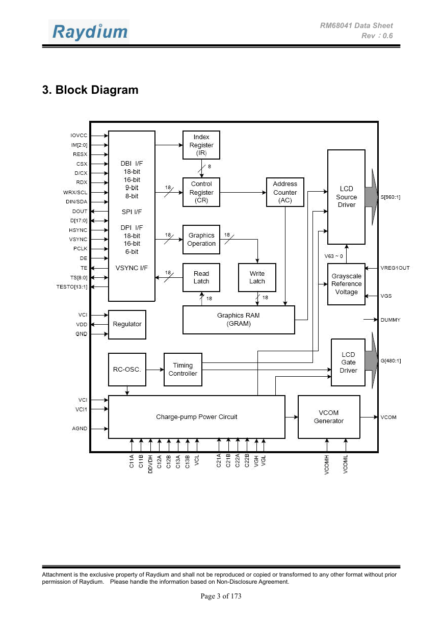
3. Block Diagram
RM68041 Data Sheet
Rev:0.6
Attachment is the exclusive property of Raydium and shall not be reproduced or copied or transformed to any other format without prior
permission of Raydium. Please handle the information based on Non-Disclosure Agreement.
Page 3 of 173
�
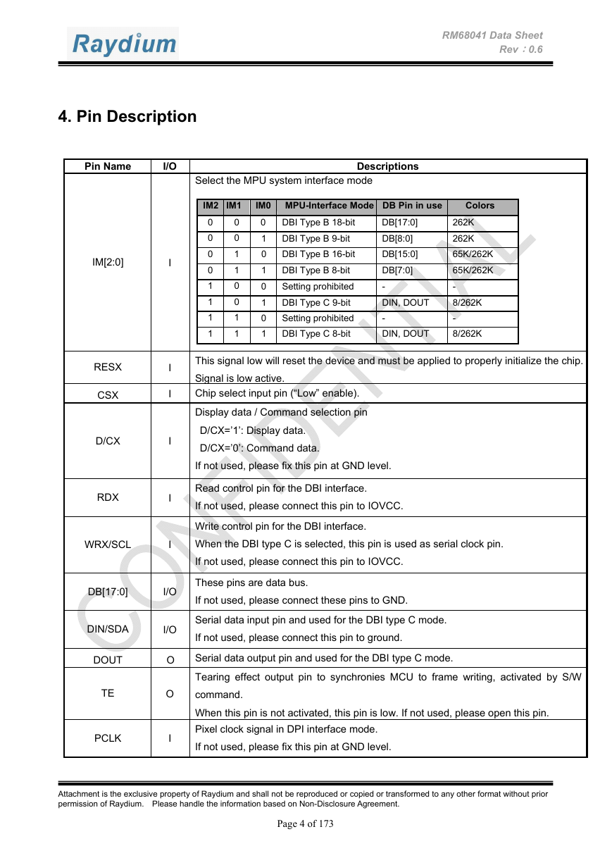
4. Pin Description
RM68041 Data Sheet
Rev:0.6
Pin Name
I/O
Select the MPU system interface mode
Descriptions
IM2 IM1
0
0
0
0
0
1
0
1
1
0
1
0
1
1
1
1
IM0 MPU-Interface Mode DB Pin in use
0 DBI Type B 18-bit
1 DBI Type B 9-bit
0 DBI Type B 16-bit
1 DBI Type B 8-bit
0
Setting prohibited
1 DBI Type C 9-bit
0
Setting prohibited
1 DBI Type C 8-bit
DB[17:0]
DB[8:0]
DB[15:0]
DB[7:0]
-
DIN, DOUT
-
DIN, DOUT
Colors
262K
262K
65K/262K
65K/262K
-
8/262K
-
8/262K
This signal low will reset the device and must be applied to properly initialize the chip.
Signal is low active.
Chip select input pin (“Low” enable).
Display data / Command selection pin
D/CX=’1’: Display data.
D/CX=’0’: Command data.
If not used, please fix this pin at GND level.
Read control pin for the DBI interface.
If not used, please connect this pin to IOVCC.
Write control pin for the DBI interface.
When the DBI type C is selected, this pin is used as serial clock pin.
If not used, please connect this pin to IOVCC.
I
I
I
I
I
I
I/O
I/O
O
O
I
These pins are data bus.
If not used, please connect these pins to GND.
Serial data input pin and used for the DBI type C mode.
If not used, please connect this pin to ground.
Serial data output pin and used for the DBI type C mode.
Tearing effect output pin to synchronies MCU to frame writing, activated by S/W
command.
When this pin is not activated, this pin is low. If not used, please open this pin.
Pixel clock signal in DPI interface mode.
If not used, please fix this pin at GND level.
IM[2:0]
RESX
CSX
D/CX
RDX
WRX/SCL
DB[17:0]
DIN/SDA
DOUT
TE
PCLK
Attachment is the exclusive property of Raydium and shall not be reproduced or copied or transformed to any other format without prior
permission of Raydium. Please handle the information based on Non-Disclosure Agreement.
Page 4 of 173
�
