CiA Draft Recommendation 303
CANopen
Additional specification
Part 3: Indicator specification
Version: 1.3
14.08.2006
CAN in Automation (CiA) e. V.
�
Additional specification – Part 3: Indicator specification
Changes
Publication of version 1.0 as draft recommendation
Publication of version 1.2 as draft recommendation
Publication of version 1.3 as draft recommendation
- minor editorial changes
HISTORY
Date
2001-07-01
2005-01-01
2006-08-14
General information on licensing and patents
CAN in AUTOMATION (CiA) calls attention to the possibility that some of the elements of this
CiA specification may be subject of patent rights. CiA shall not be responsible for identifying
any or all such patent rights.
Because this specification is licensed free of charge, there is no warranty for this
specification, to the extent permitted by applicable law. Except when otherwise stated in
writing the copyright holder and/or other parties provide this specification “as is” without
warranty of any kind, either expressed or implied, including, but not limited to, the implied
warranties of merchantability and fitness for a particular purpose. The entire risk as to the
correctness and completeness of the specification is with you. Should this specification prove
failures, you assume the cost of all necessary servicing, repair or correction.
© CiA 2008
All rights reserved. Unless otherwise specified, no part of this publication may be reproduced or
utilized in any form or by any means, electronic or mechanical, including photocopying and microfilm,
without permission in writing from CiA at the address below.
CAN in Automation e. V.
Kontumazgarten 3
DE - 90429 Nuremberg, Germany
Tel.: +49-911-928819-0
Fax: +49-911-928819-79
Url: www.can-cia.org
Email: headquarters@can-cia.org
2
CiA 2008 – All rights reserved
�
Additional specification – Part 3: Indicator specification
CONTENTS
1 Scope ............................................................................................................................... 4
2 References ....................................................................................................................... 4
3 Abbreviations and definitions ............................................................................................ 4
3.1 Abbreviations........................................................................................................... 4
3.2 Definitions ............................................................................................................... 4
3.2.1 General ....................................................................................................... 4
3.2.2 Using two CANopen LEDs ........................................................................... 4
3.2.3 Using one bicolor CANopen LED ................................................................. 4
Indicators.......................................................................................................................... 4
Introduction ............................................................................................................. 4
4.1
4.2
Indicator states and flash rates ................................................................................ 5
4.3 CANopen error LED................................................................................................. 6
4.4 CANopen run LED ................................................................................................... 7
4.5 CANopen status LED............................................................................................... 7
4
CiA 2008 – All rights reserved
3
�
Additional specification – Part 3: Indicator specification
1 Scope
A common behavior of indicators helps service personnel to identify communication problems
quickly without checking manuals for each device. This recommendation intends to specify
the implementation of status LEDs (Light Emitting Diode) on CANopen devices.
indicators. Additional
This recommendation only describes
application-related indicators can be present. Their use is either described in the appropriate
device profile or is manufacturer specific.
the communication-related
2 References
/CiA301/
CiA DS 301, CANopen application layer and communication profile
3 Abbreviations and definitions
3.1 Abbreviations
LED
Light emitting diode
ERR Error
I/O
Input/output
3.2 Definitions
3.2.1
General
The definitions given in /CiA301/ apply to this draft recommendation too. As the manufacturer
is free to use one bicolor LED or two single LEDs, the corresponding of the two following
definitions shall apply.
3.2.2
Using two CANopen LEDs
In case of using two single CANopen LEDs, the following definitions shall apply:
One LED shall be red and shall be labeled as ERR LED. This LED shall be called the
error LED
The other LED shall be green and shall be called and labeled as RUN LED.
3.2.3
Using one bicolor CANopen LED
In case of using one bicolor CANopen LED the following definitions shall apply:
The colors provided by the LED shall be red and green
The LED shall be labeled as STATUS LED
4 Indicators
4.1
Introduction
It is either recommended to support two single CANopen LEDs or one bicolor LED. Additional
LEDs for power indication, I/O functionality etc. may also exist.
4
CiA 2008 – All rights reserved
�
4.2
Additional specification – Part 3: Indicator specification
Indicator states and flash rates
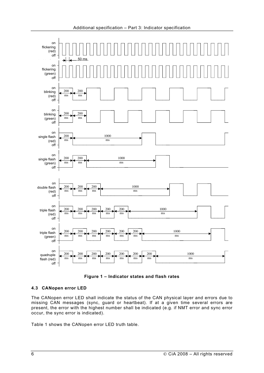
The following indicator states are defined:
LED on
LED off
LED flickering
LED blinking
The LED shall be constantly on.
The LED shall be constantly off.
shall
indicate
approximately
10 Hz: on for approximately 50 ms and off for approximately 50 ms.
iso-phase on and off with a
the
frequency of
the
shall
indicate
approximately
2,5 Hz: on for approximately 200 ms followed by off for approximately
200 ms.
iso-phase on and off with a
frequency of
LED single flash
shall indicate one short flash (approximately 200 ms) followed by a long
off phase (approximately 1000 ms).
LED double flash
shall indicate a sequence of two short flashes (approximately 200 ms),
separated by an off phase (approximately 200 ms). The sequence is
finished by a long off phase (approximately 1000 ms).
LED triple flash
shall indicate a sequence of three short flashes (approximately 200
ms), separated by an off phase (approximately 200 ms). The sequence
is finished by a long off phase (approximately 1000 ms).
LED quadruple flash shall indicate a sequence of four short flashes (approximately 200 ms),
separated by an off phase (approximately 200 ms). The sequence is
finished by a long off phase (approximately 1000 ms).
Figure 1 shows the indicator states and flash rates.
CiA 2008 – All rights reserved
5
�
Additional specification – Part 3: Indicator specification
Figure 1 – Indicator states and flash rates
4.3 CANopen error LED
The CANopen error LED shall indicate the status of the CAN physical layer and errors due to
missing CAN messages (sync, guard or heartbeat). If at a given time several errors are
present, the error with the highest number shall be indicated (e.g. if NMT error and sync error
occur, the sync error is indicated).
Table 1 shows the CANopen error LED truth table.
6
CiA 2008 – All rights reserved
onsingle flash(green)off200ms200ms1000msonsingle flash(red)off1000ms200msonblinking(red)off200ms200msonflickering(red)offonflickering(green)off50 msonblinking(green)off200ms200msdouble flashontriple flash(red)off200ms200ms200ms200ms200ms1000msondouble flash(red)off200ms200ms200ms1000msontriple flash(green)off200ms200ms200ms200ms200ms1000ms200msonquadruple flash (red)off200ms200ms200ms200ms200ms1000ms200ms200ms�
Additional specification – Part 3: Indicator specification
Table 1 – CANopen error LED truth table
ERR LED
State
Description
Category
Off
Flickering
No error
AutoBitrate/
LSS
Blinking
Single flash
Invalid
Configuration
Warning limit
reached
The device is in working condition
Mandatory
The auto-bitrate detection is in
progress or LSS services are in
progress (alternately flickering with
run LED)1
General configuration error
At least one of the error counters of
the CAN controller has reached or
exceeded the warning level (too
many error frames)
Optional
Optional
Mandatory
Double flash
Error control event A guard event (NMT-slave or NMT-
master) or a heartbeat event
(heartbeat consumer) has occurred
Mandatory
Triple flash
Sync error
Quadruple
flash
Event-timer error
The sync message has not been
received within the configured
communication cycle period time out
(see object dictionary entry 1006h)
An expected PDO has not been
received before the event-timer
elapsed
Conditional;
Mandatory if object
1006h is supported
Optional
On
Bus off
The CAN controller is bus off
Mandatory
4.4 CANopen run LED
The CANopen run LED shall indicate the status of the CANopen network state machine.
Whilst the device is executing a reset the CANopen run LED shall be off.
Table 2 shows the CANopen Run LED truth table.
Table 2 – CANopen Run LED truth table
CAN Run LED
Flickering
State
AutoBitrate/LSS
Description
The auto-bitrate detection is in progress
or LSS services are in progress
(alternately flickering with error LED)
Blinking
PRE-
OPERATIONAL
The device is in state PRE-
OPERATIONAL
Category
Optional
Mandatory
Single flash
STOPPED
The device is in state STOPPED
Mandatory
Double flash
Triple flash
Program/ Firmware
download
Reserved for further use
A software download is running on the
device
Optional
On
OPERATIONAL
The device is in state OPERATIONAL Mandatory
4.5 CANopen status LED
If one bicolor status LED is used instead of two single color LEDs, this LED shall indicate both
the physical bus status and the status of the CANopen state machine.
In case there is a conflict between turning the LED on green versus red, the LED may be
turned on red. Apart from this situation, the bicolor status LED shall combine the behavior of
the CAN error LED and those of the CAN run LED.
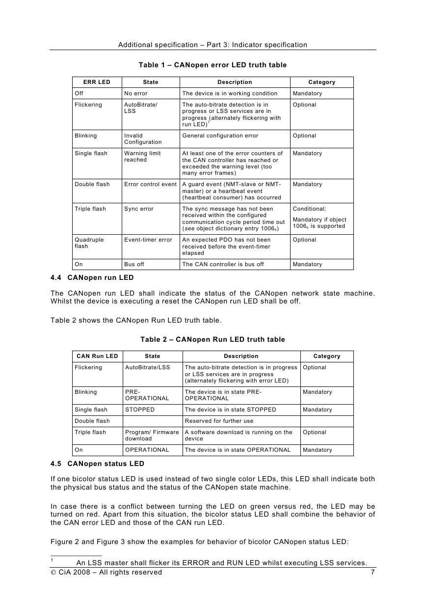
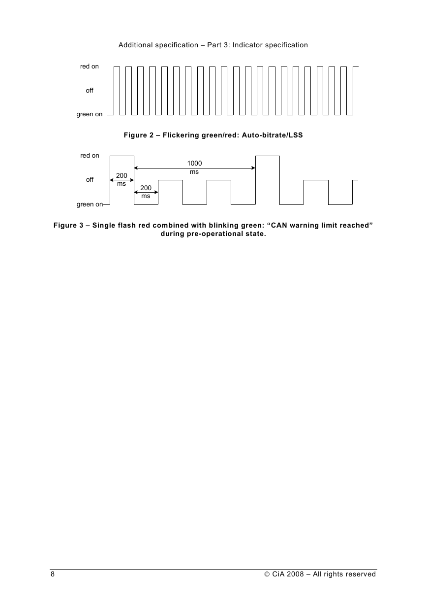
Figure 2 and Figure 3 show the examples for behavior of bicolor CANopen status LED:
—————————
1
CiA 2008 – All rights reserved
An LSS master shall flicker its ERROR and RUN LED whilst executing LSS services.
7
�
Additional specification – Part 3: Indicator specification
Figure 2 – Flickering green/red: Auto-bitrate/LSS
Figure 3 – Single flash red combined with blinking green: “CAN warning limit reached”
during pre-operational state.
8
CiA 2008 – All rights reserved
red onoffgreen onred onoffgreen on200ms200ms1000ms�
