MODBUS over serial line specification and implementation guide V1.02
Modbus.org
MODBUS over Serial Line
Specification and Implementation Guide
V1.02
Modbus.org
Dec 20, 2006
http://www.modbus.org/
1/44
�
MODBUS over serial line specification and implementation guide V1.02
Modbus.org
Contents
1
Introduction ..............................................................................4
1.1 Scope of this document ............................................................. 4
1.2 Protocol overview....................................................................... 5
1.3 Conventions ............................................................................... 5
1.4 Compliance ................................................................................ 6
1.5 Glossary..................................................................................... 6
2 MODBUS Data Link Layer.......................................................7
2.1 MODBUS Master / Slaves protocol principle.............................. 7
2.2 MODBUS Addressing rules........................................................ 8
2.3 MODBUS frame description....................................................... 8
2.4 Master / Slaves State Diagrams................................................. 9
2.5 The two serial Transmission Modes......................................... 12
2.6 Error Checking Methods .......................................................... 19
3 Physical Layer........................................................................20
3.1 Preamble.................................................................................. 20
3.2 Data Signaling Rates ............................................................... 20
3.3 Electrical Interfaces.................................................................. 21
3.4 Multipoint System requirements............................................... 27
3.5 Mechanical Interfaces .............................................................. 29
3.6 Cables...................................................................................... 32
3.7 Visual Diagnosis ...................................................................... 32
Installation and Documentation .............................................33
4.1
Installation................................................................................ 33
4.2 User Guide............................................................................... 33
5
Implementation Classes ........................................................34
6 Appendix................................................................................35
6.1 Appendix A - Management of Serial Line Diagnostic Counters35
6.2 Appendix B - LRC/CRC Generation......................................... 38
6.3 Appendix E - References ......................................................... 44
4
Modbus.org
Dec 20, 2006
http://www.modbus.org/
2/44
�
MODBUS over serial line specification and implementation guide V1.02
Modbus.org
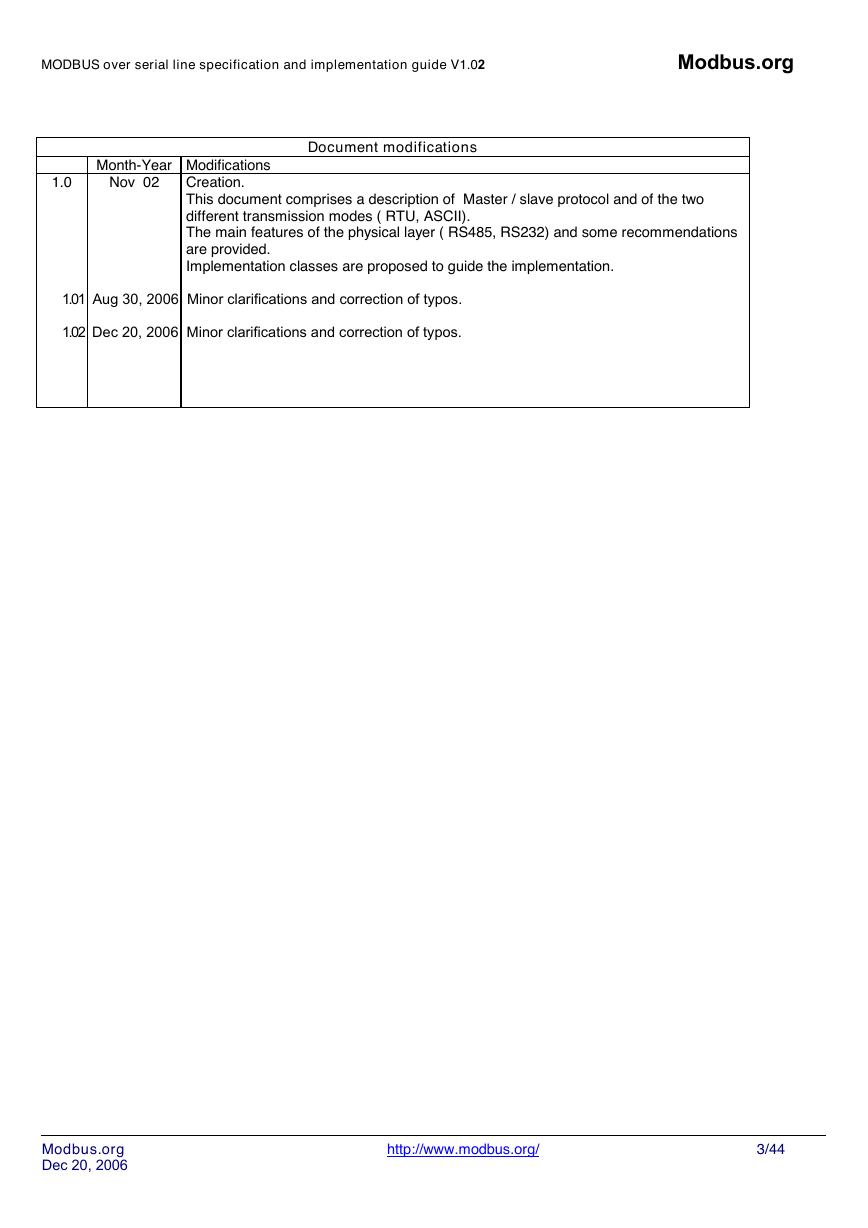
1.0
Month-Year Modifications
Nov 02
Document modifications
Creation.
This document comprises a description of Master / slave protocol and of the two
different transmission modes ( RTU, ASCII).
The main features of the physical layer ( RS485, RS232) and some recommendations
are provided.
Implementation classes are proposed to guide the implementation.
1.01 Aug 30, 2006 Minor clarifications and correction of typos.
1.02 Dec 20, 2006 Minor clarifications and correction of typos.
Modbus.org
Dec 20, 2006
http://www.modbus.org/
3/44
�
MODBUS over serial line specification and implementation guide V1.02
Modbus.org
1
Introduction
1.1 Scope of this document
The MODBUS standard defines an application layer messaging protocol, positioned at level 7 of the OSI model that provides
"client/server" communications between devices connected on different types of buses or networks. It standardizes also a specific
protocol on serial line to exchange MODBUS request between a master and one or several slaves.
The objective of this document is to present the MODBUS protocol over serial line, in order to be used by all system designers when
they want to implement MODBUS protocol on their serial line products. Thus, this document will facilitate interoperability between
devices using the MODBUS protocol.
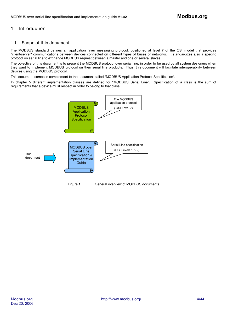
This document comes in complement to the document called "MODBUS Application Protocol Specification".
In chapter 5 different implementation classes are defined for "MODBUS Serial Line". Specification of a class is the sum of
requirements that a device must respect in order to belong to that class.
The MODBUS
application protocol
( OSI Level 7)
MODBUS
Application
Protocol
Specification
This
document
MODBUS over
Serial Line
Specification &
Implementation
Guide
Serial Line specification
(OSI Levels 1 & 2)
Figure 1:
General overview of MODBUS documents
Modbus.org
Dec 20, 2006
http://www.modbus.org/
4/44
�
MODBUS over serial line specification and implementation guide V1.02
Modbus.org
1.2 Protocol overview
This document describes the MODBUS over Serial Line protocol. MODBUS Serial Line protocol is a Master-Slave protocol. This
protocol takes place at level 2 of the OSI model.
A master-slave type system has one node (the master node) that issues explicit commands to one of the "slave" nodes and processes
responses. Slave nodes will not typically transmit data without a request from the master node, and do not communicate with other
slaves.
At the physical level, MODBUS over Serial Line systems may use different physical interfaces (RS485, RS232). TIA/EIA-485 (RS485)
Two-Wire interface is the most common. As an add-on option, RS485 Four-Wire interface may also be implemented. A TIA/EIA-232-
E (RS232) serial interface may also be used as an interface, when only short point to point communication is required. (see chapter
"Physical Layer")
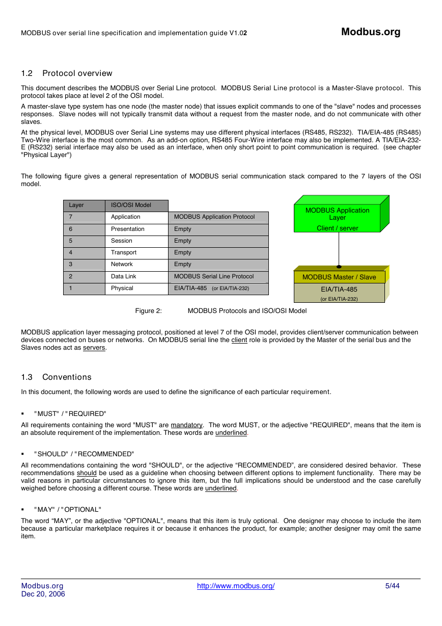
The following figure gives a general representation of MODBUS serial communication stack compared to the 7 layers of the OSI
model.
Layer
7
6
5
4
3
2
1
ISO/OSI Model
Application
Presentation
Session
Transport
Network
Data Link
Physical
MODBUS Application Protocol
Empty
Empty
Empty
Empty
MODBUS Serial Line Protocol
EIA/TIA-485 (or EIA/TIA-232)
MODBUS Application
Layer
Client / server
MODBUS Master / Slave
EIA/TIA-485
(or EIA/TIA-232)
Figure 2:
MODBUS Protocols and ISO/OSI Model
MODBUS application layer messaging protocol, positioned at level 7 of the OSI model, provides client/server communication between
devices connected on buses or networks. On MODBUS serial line the client role is provided by the Master of the serial bus and the
Slaves nodes act as servers.
1.3 Conventions
In this document, the following words are used to define the significance of each particular requirement.
� "MUST" / "REQUIRED"
All requirements containing the word "MUST" are mandatory. The word MUST, or the adjective "REQUIRED", means that the item is
an absolute requirement of the implementation. These words are underlined.
� "SHOULD" / "RECOMMENDED"
All recommendations containing the word "SHOULD", or the adjective “RECOMMENDED”, are considered desired behavior. These
recommendations should be used as a guideline when choosing between different options to implement functionality. There may be
valid reasons in particular circumstances to ignore this item, but the full implications should be understood and the case carefully
weighed before choosing a different course. These words are underlined.
� "MAY" / "OPTIONAL"
The word “MAY”, or the adjective "OPTIONAL", means that this item is truly optional. One designer may choose to include the item
because a particular marketplace requires it or because it enhances the product, for example; another designer may omit the same
item.
Modbus.org
Dec 20, 2006
http://www.modbus.org/
5/44
�
MODBUS over serial line specification and implementation guide V1.02
Modbus.org
1.4 Compliance
An implementation is not in conformity if it fails to satisfy one or more of the MUST requirements from its implementation class.
An implementation that satisfies all the MUST requirements and all the SHOULD recommendations is said to be "unconditionally
compliant".
One that satisfies all the MUST requirements but not all the SHOULD recommendations is said to be "conditionally compliant".
1.5 Glossary
Definition of particular words, symbols, and abbreviations used in this document.
2W
4W
AUI
AWG
Common
DCE
Device
Driver
DTE
ITr
IDv
LT
MODBUS Device
RS232
RS485
RS485-MODBUS
Transceiver
The Two-Wire configuration defined in the “Electrical Interface” chapter, or one of its interfaces.
The Four-Wire configuration defined in the “Electrical Interface” chapter, or one of its interfaces.
Attachment Unit Interface
American Wire Gauge, a standard method denoting wire diameter; please see Appendix E - References.
The Signal Common in EIA/TIA Standards. In a 2W-or 4W-RS485 MODBUS Network, Signal and optional
Power Supply Common
a MODBUS Device, for example a programmable controller adapter, which implements an RS232 Data
Circuit-terminating Equipment, also named Data Communication Equipment.
or “MODBUS device” : see this definition.
Generator, or Transmitter.
a MODBUS Device, for example a programming panel or a PC, which implements an RS232 Data
Terminal Equipment.
Physical bus Interface on Trunk side.
Physical bus Interface on Derivation (or tap or device drop) side.
Line Termination.
a Device that implements MODBUS over Serial Line and respects this Technical Note.
EIA/ TIA -232 Standard.
EIA/ TIA -485 Standard.
A 2W-or 4W-Network in accordance with this Technical Note.
a Transmitter and a Receiver (or Driver and Receiver).
Modbus.org
Dec 20, 2006
http://www.modbus.org/
6/44
�
MODBUS over serial line specification and implementation guide V1.02
Modbus.org
2 MODBUS Data Link Layer
2.1 MODBUS Master / Slaves protocol principle
The MODBUS Serial Line protocol is a Master-Slaves protocol. Only one master (at the same time) is connected to the bus, and one
or several (247 maximum number) slaves nodes are also connected to the same serial bus. A MODBUS communication is always
initiated by the master. The slave nodes will never transmit data without receiving a request from the master node. The slave nodes
will never communicate with each other. The master node initiates only one MODBUS transaction at the same time.
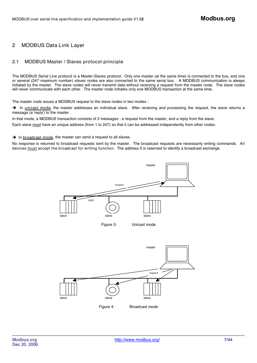
The master node issues a MODBUS request to the slave nodes in two modes :
� In unicast mode, the master addresses an individual slave. After receiving and processing the request, the slave returns a
message (a 'reply') to the master .
In that mode, a MODBUS transaction consists of 2 messages : a request from the master, and a reply from the slave.
Each slave must have an unique address (from 1 to 247) so that it can be addressed independently from other nodes.
� In broadcast mode, the master can send a request to all slaves.
No response is returned to broadcast requests sent by the master. The broadcast requests are necessarily writing commands. All
devices must accept the broadcast for writing function. The address 0 is reserved to identify a broadcast exchange.
master
request
reply
slave
slave
slave
Figure 3:
Unicast mode
master
request
slave
slave
slave
Figure 4:
Broadcast mode
Modbus.org
Dec 20, 2006
http://www.modbus.org/
7/44
�
MODBUS over serial line specification and implementation guide V1.02
Modbus.org
2.2 MODBUS Addressing rules
The MODBUS addressing space comprises 256 different addresses.
0
Broadcast
address
From 1 to 247
Slave individual addresses
From 248 to 255
Reserved
The Address 0 is reserved as the broadcast address. All slave nodes must recognise the broadcast address.
The MODBUS Master node has no specific address, only the slave nodes must have an address. This address must be unique on a
MODBUS serial bus.
2.3 MODBUS frame description
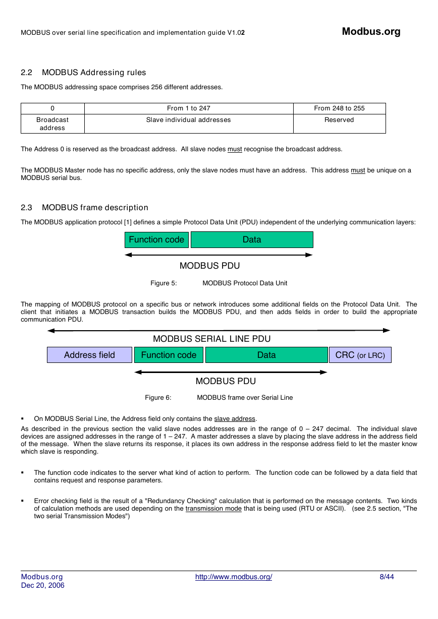
The MODBUS application protocol [1] defines a simple Protocol Data Unit (PDU) independent of the underlying communication layers:
Function code
Data
MODBUS PDU
Figure 5:
MODBUS Protocol Data Unit
The mapping of MODBUS protocol on a specific bus or network introduces some additional fields on the Protocol Data Unit. The
client that initiates a MODBUS transaction builds the MODBUS PDU, and then adds fields in order to build the appropriate
communication PDU.
Address field
MODBUS SERIAL LINE PDU
Data
Function code
CRC (or LRC)
MODBUS PDU
Figure 6:
MODBUS frame over Serial Line
� On MODBUS Serial Line, the Address field only contains the slave address.
As described in the previous section the valid slave nodes addresses are in the range of 0 – 247 decimal. The individual slave
devices are assigned addresses in the range of 1 – 247. A master addresses a slave by placing the slave address in the address field
of the message. When the slave returns its response, it places its own address in the response address field to let the master know
which slave is responding.
� The function code indicates to the server what kind of action to perform. The function code can be followed by a data field that
contains request and response parameters.
� Error checking field is the result of a "Redundancy Checking" calculation that is performed on the message contents. Two kinds
of calculation methods are used depending on the transmission mode that is being used (RTU or ASCII). (see 2.5 section, "The
two serial Transmission Modes")
Modbus.org
Dec 20, 2006
http://www.modbus.org/
8/44
�

