SOLOMON SYSTECH
SEMICONDUCTOR TECHNICAL DATA
SSD1289
Advance Information
240 RGB x 320 TFT LCD Controller Driver
integrated Power Circuit, Gate and Source Driver
with built-in RAM
This document contains information on a new product. Specifications and information herein are subject to change
without notice.
http://www.solomon-systech.com
SSD1289
Copyright © 2006 Solomon Systech Limited
Sep 2006
Rev 1.1
P 1/81
�
CONTENTS
GENERAL DESCRIPTION ......................................................................................... 5
1
FEATURES................................................................................................................. 6
2
ORDERING INFORMATION....................................................................................... 7
3
BLOCK DIAGRAM ..................................................................................................... 8
4
DIE PAD FLOOR PLAN ............................................................................................. 9
5
PIN DESCRIPTION................................................................................................... 17
6
BLOCK FUNCTION DESCRIPTION......................................................................... 21
7
COMMAND TABLE .................................................................................................. 24
8
9
COMMAND DESCRIPTION...................................................................................... 27
10 GAMMA ADJUSTMENT FUNCTION ....................................................................... 53
11 MAXIMUM RATINGS................................................................................................ 60
12 DC CHARACTERISTICS.......................................................................................... 60
13 AC CHARACTERISTICS.......................................................................................... 62
14 GDDRAM ADDRESS................................................................................................ 67
15
INTERFACE MAPPING............................................................................................ 68
16 DISPLAY SETTING SEQUENCE ............................................................................. 71
17 POWER SUPPLY BLOCK DIAGRAM...................................................................... 74
18 SSD1289 OUTPUT VOLTAGE RELATIONSHIP ..................................................... 75
19 APPLICATION CIRCUIT .......................................................................................... 76
20 PACKAGE INFORMATION...................................................................................... 80
Solomon Systech
Sep 2006 P 2/81
Rev 1.1
SSD1289
�
TABLES
Table 3-1 – Ordering Information......................................................................................................... 7
Table 5-1 - SSD1289 Bump Pad Coordinate (Bump Center)............................................................. 10
Table 6-1: Power Supply Pins ............................................................................................................ 17
Table 6-2 - Interface Logic Pins ......................................................................................................... 18
Table 6-3: Mode Selection Pins.......................................................................................................... 19
Table 6-4: Driver Output Pins............................................................................................................. 20
Table 6-5: Miscellaneous Pins............................................................................................................ 20
Table 7-1 - Data bus selection modes................................................................................................. 22
Table 7-2: RGB signal matching in data bus...................................................................................... 22
Table 8-1 - Command Table............................................................................................................... 24
Table 8-2 – Gamma Registers POR value .......................................................................................... 26
Table 8-3: Registers POR value at GAMAS[2:0] = 000,100 ............................................................. 26
Table 8-4: Registers POR value at GAMAS[2:0] = 001,101 ............................................................. 26
Table 8-5: Registers POR value at GAMAS[2:0] = 010,110 ............................................................. 26
Table 8-6: Registers POR value at GAMAS[2:0] = 011,111 ............................................................. 26
Table 9-1: 3-field interlace driving..................................................................................................... 31
Table 13-1 – Parallel 6800 Timing Characteristics (TA = -20 to 70°C, VDDIO = 1.4V to 3.6V, VDDEXT
= 1.4V – 1.95V, REGVDD=’L’) ................................................................................................ 62
Table 13-2 – Parallel 8080 Timing Characteristics ............................................................................ 63
Table 13-3 - Serial Timing Characteristics......................................................................................... 64
Table 15-1: Interface setting and data bus setting .............................................................................. 68
Table 15-2 – The Function of 6800-series parallel interface.............................................................. 68
Table 15-3 ........................................................................................................................................... 69
SSD1289
Rev 1.1
P 3/81
Sep 2006
Solomon Systech
�
FIGURES
Figure 4-1 - SSD1289 Block Diagram Description.............................................................................. 8
Figure 5-1 - SSD1289 Pad Arrangement (Bump face up).................................................................... 9
Figure 7-1 – Read Display Data.......................................................................................................... 21
Figure 9-1: gate output timing in 3-field interlacing driving.............................................................. 31
Figure 9-2: Line Inversion AC Driver ................................................................................................ 32
Figure 9-3 – OTP circuitry.................................................................................................................. 48
Figure 13-1 –Parallel 6800-series Interface Timing Characteristics .................................................. 62
Figure 13-2 –Parallel 8080-series Interface Timing Characteristics .................................................. 63
Figure 13-3 – 4 wire Serial Timing Characteristics............................................................................ 64
Figure 13-4 - Pixel Clock Timing in RGB interface mode................................................................. 65
Figure 17-1 - Booster Capacitors........................................................................................................ 76
Figure 17-2 – Filtering and charge sharing capacitors........................................................................ 76
Figure 17-3 – Power supply pin connection ....................................................................................... 77
Figure 17-4 – Panel Connection Example .......................................................................................... 78
Figure 17-5 - ITO and FPC connection example................................................................................ 79
Solomon Systech
Sep 2006 P 4/81
Rev 1.1
SSD1289
�
1 GENERAL DESCRIPTION
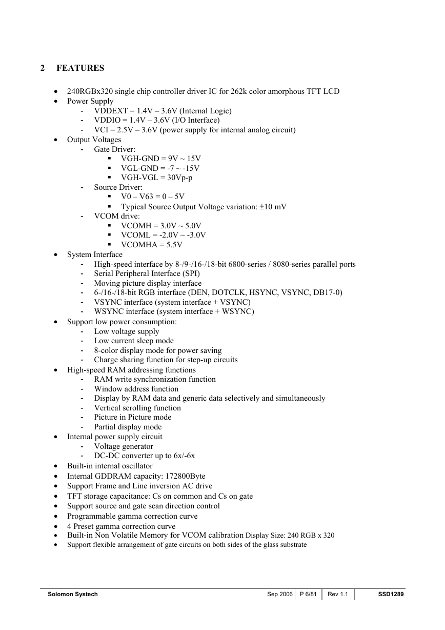
SSD1289 is an all in one TFT LCD Controller Driver that integrated the RAM, power circuits, gate driver and
source driver into a single chip. It can drive up to 262k color amorsphous TFT panel with resolution of 240 RGB x 320.
It also integrated the controller function and consists of 172,800 bytes (240 x 320 x 18 / 8) Graphic Display Data RAM
(GDDRAM) such that it interfaced with common MPU through 8-/9-/16-/18-bit 6800-series / 8080-series compatible
parallel interface or serial peripheral interface and stored the data in the GDDRAM. Auxiliary 18-/16-/6-bit video
interface (VSYNC, HSYNC, DOTCLK, DEN) are integrated into SSD1289 for animation image display.
SSD1289 embeds DC-DC Converter and Voltage generator to provide all necessary voltage required by the driver with
minimum external components. A Common Voltage Generation Circuit is included to drive the TFT-display counter
electrode. An Integrated Gamma Control Circuit is also included that can be adjusted by software commands to provide
maximum flexibility and optimal display quality.
SSD1289 can be operated down to 1.4V and provide different power save modes. It is suitable for any portable battery-
driven applications requiring long operation period and compact size.
SSD1289
Rev 1.1
P 5/81
Sep 2006
Solomon Systech
�
2 FEATURES
• 240RGBx320 single chip controller driver IC for 262k color amorphous TFT LCD
• Power Supply
- VDDEXT = 1.4V – 3.6V (Internal Logic)
- VDDIO = 1.4V – 3.6V (I/O Interface)
- VCI = 2.5V – 3.6V (power supply for internal analog circuit)
• Output Voltages
- Gate Driver:
VGH-GND = 9V ~ 15V
VGL-GND = -7 ~ -15V
VGH-VGL = 30Vp-p
- Source Driver:
- VCOM drive:
V0 – V63 = 0 – 5V
Typical Source Output Voltage variation: ±10 mV
VCOMH = 3.0V ~ 5.0V
VCOML = -2.0V ~ -3.0V
VCOMHA = 5.5V
• System Interface
- High-speed interface by 8-/9-/16-/18-bit 6800-series / 8080-series parallel ports
- Serial Peripheral Interface (SPI)
- Moving picture display interface
-
- VSYNC interface (system interface + VSYNC)
- WSYNC interface (system interface + WSYNC)
6-/16-/18-bit RGB interface (DEN, DOTCLK, HSYNC, VSYNC, DB17-0)
• Support low power consumption:
- Low voltage supply
- Low current sleep mode
-
- Charge sharing function for step-up circuits
8-color display mode for power saving
• High-speed RAM addressing functions
- RAM write synchronization function
- Window address function
- Display by RAM data and generic data selectively and simultaneously
- Vertical scrolling function
- Picture in Picture mode
- Partial display mode
Internal power supply circuit
•
- Voltage generator
- DC-DC converter up to 6x/-6x
Internal GDDRAM capacity: 172800Byte
• Built-in internal oscillator
•
• Support Frame and Line inversion AC drive
• TFT storage capacitance: Cs on common and Cs on gate
• Support source and gate scan direction control
• Programmable gamma correction curve
• 4 Preset gamma correction curve
• Built-in Non Volatile Memory for VCOM calibration Display Size: 240 RGB x 320
• Support flexible arrangement of gate circuits on both sides of the glass substrate
Solomon Systech
Sep 2006 P 6/81
Rev 1.1
SSD1289
�
3 ORDERING INFORMATION
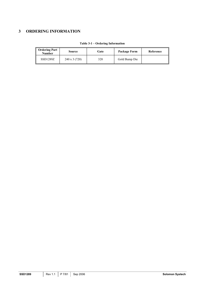
Table 3-1 – Ordering Information
Ordering Part
Number
SSD1289Z
Source
240 x 3 (720)
Gate
320
Package Form
Reference
Gold Bump Die
SSD1289
Rev 1.1
P 7/81
Sep 2006
Solomon Systech
�
4 BLOCK DIAGRAM
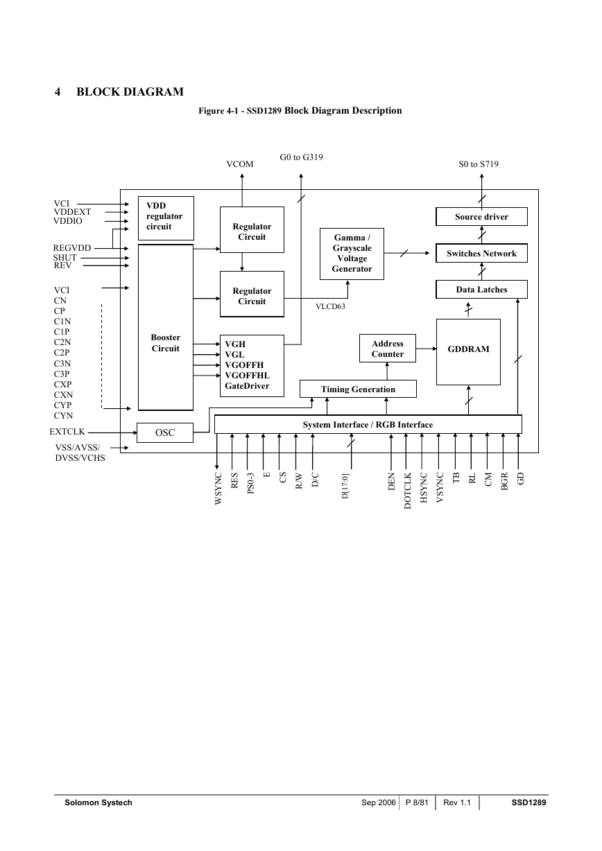
Figure 4-1 - SSD1289 Block Diagram Description
VCI
VDDEXT
VDDIO
REGVDD
SHUT
REV
VCI
CN
CP
C1N
C1P
C2N
C2P
C3N
C3P
CXP
CXN
CYP
CYN
EXTCLK
VSS/AVSS/
DVSS/VCHS
VCOM
G0 to G319
S0 to S719
Regulator
Circuit
Regulator
Circuit
VGH
VGL
VGOFFH
VGOFFHL
GateDriver
Gamma /
Grayscale
Voltage
Generator
VLCD63
Source driver
Switches Network
Data Latches
Address
Counter
GDDRAM
Timing Generation
System Interface / RGB Interface
VDD
regulator
circuit
Booster
Circuit
OSC
S
E
R
3
-
0
S
P
E
S
C
W
R
/
C
N
Y
S
W
/
C
D
]
0
:
7
1
[
D
N
E
D
C
N
Y
S
H
C
N
Y
S
V
K
L
C
T
O
D
B
T
L
R
M
C
D
G
R
G
B
Solomon Systech
Sep 2006 P 8/81
Rev 1.1
SSD1289
�
