CAN in Automation e. V.
Framework for Programmable CANopen Devices
CiA Draft Standard Proposal 302
Not recommended for implementation
May be changed without notification
Version 3.1.1
Date: 10.05.2002
ª
ª
ª
ª
�
CiA DSP-302 V3.1.1
Framework for Programmable CANopen Devices
CiA e.V.
History
Date
Version Changes
05.03.1998 1.0
Initial revision
27.11.1998 2.0
29.06.2000 3.0
07.03.2002 3.1
• New chapter for NMT Master related objects
• Extension of Configuration Manager
• Groups / Multiplexor PDO: Clarification and new objects for con-
figuration
Introduced definition of the boot-up procedure
•
• Renamed chapter Slave Assignment to Network List
• New objects for the network list
• Clarification of existing objects according to DS-301 V4
• Moved chapter Configuration Master behind chapter NMT Mas-
ter
• New objects for the Configuration Manager
• Adaptation of Client/Server relationships to Producer/Consumer
model according to DS-301 V4. Removed references to CAL.
• Network variables may have access type rww
• Removed duplicated example in section 8.3
• Moved data type declaration 23H to 25H due to overlap with DS-
301 V4
• Moved objects 1020H Verify Configuration, 1021H/1022H EDS
Storage to appendix of DS-301
• Moved chapter OS Command and Prompt to appendix of DS-
301
• Moved chapter Groups to appendix of DS-301
• Change of SDO Manager Mechanisms
• Definition of CANopen Manager includes now the case NMT
Master + Configuration Manager
• Self-starting devices
• Flying Master taken over from SIG Maritime with some changes
• Updated references
• Object 1F81H, Bit 1 has become obsolete by the defined proc-
esses; removed
• Clarification of object attribute M/O
• Editorial changes
• Added Error Codes
• Bug fixes and clarifications
08.05.2002 3.1.1
- I -
�
CiA DSP-302 V3.1.1
Framework for Programmable CANopen Devices
CiA e.V.
Table of Contents
1 Scope........................................................................................................................................... 1
2 References .................................................................................................................................. 1
3 CANopen Manager, Terms and Definitions ............................................................................. 2
4 Boot-Up Procedure .................................................................................................................... 3
5 NMT Master............................................................................................................................... 16
5.1 NMT Start-up ....................................................................................................................... 16
5.2 Network List ......................................................................................................................... 18
5.3 Error Control ........................................................................................................................ 20
5.4 Request NMT....................................................................................................................... 22
5.5 Flying Master ....................................................................................................................... 24
6 Configuration Manager............................................................................................................ 34
6.1 DCF storage......................................................................................................................... 34
6.2 Concise configuration storage ............................................................................................. 35
6.3 Check configuration process .............................................................................................. 36
6.4 Request Configuration ......................................................................................................... 36
6.5 EDS storage......................................................................................................................... 37
7 Dynamic Establishment of SDO Connections....................................................................... 38
7.1 Basic mechanism................................................................................................................. 38
7.2 Specification......................................................................................................................... 40
8
Input/Output of a Programmable Device ............................................................................... 47
8.1 Basics .................................................................................................................................. 47
8.2 Dynamic Index Assignment ................................................................................................. 47
8.3 EDS...................................................................................................................................... 48
8.4 DCF...................................................................................................................................... 49
9 Program Download .................................................................................................................. 50
10
Summary of object dictionary extensions ...................................................................... 52
- II -
�
CiA DSP-302 V3.1.1
Framework for Programmable CANopen Devices
CiA e.V.
Figures
Figure 1: CANopen boot-up procedure main flow, part 1.............................................................3
Figure 2: CANopen boot-up procedure main flow, part 2.............................................................5
Figure 3 : Start Boot Slave Process ..............................................................................................6
Boot slave predefined process, part 1...........................................................................7
Figure 4:
Boot slave predefined process, part 2 (optional)...........................................................9
Figure 5:
Figure 6:
Check node state -predefined process. ......................................................................10
Figure 7:
Check and update software version -predefined process ..........................................11
Figure 8 : Boot slave predefined process, part 3.........................................................................12
Figure 9:
Check configuration -predefined process....................................................................13
Figure 10: Simplest possible NMT Boot Process .........................................................................15
Figure 11: Start Error Control Service -predefined process. ........................................................21
Figure 12: Error Handler...............................................................................................................22
Figure 13: Flying Master Process Overview.................................................................................25
Figure 14: Detection of Active NMT Master Protocol ...................................................................26
Figure 15: NMT Master Negotiation Protocol ...............................................................................27
Figure 16: Waiting Period after Reception of the Trigger Time Slot Command...........................28
Figure 17: Forcing a New NMT Master Negotiation Protocol.......................................................28
Figure 18: Detection of NMT Master Capable Devices ................................................................29
- III -
�
CiA DSP-302 V3.1.1
Framework for Programmable CANopen Devices
CiA e.V.
1 Scope
The CANopen Communication Profile (DS-301) defines the basic communication mechanisms for
exchanging data via a CANopen-based networks. This includes the structure of the object diction-
ary, the network management and boot-up as well as communication objects like PDO, SDO,
SYNC and time stamp. The object dictionary provides a standard interface for accessing of com-
munication parameters as well as process data. The part of the object dictionary which describes
the general device and communication parameters is common for all devices types.
Application specific functionalities which are provided by certain device types are detailed in specific
device profiles (DS-4xx). A device profile is always based upon the definitions in the communication
profile.
In general the mechanisms which are specified in the communication profile are sufficient for the
definition of profiles for devices which, on the application level, provide some kind of I/O functional-
ity. Example devices include I/O modules, drives and regulators. These devices whilst they may be
complex are not termed ‘intelligent’ as they do not run an application level program.
For the description and operation of intelligent devices further mechanisms are necessary which are
specified in DS-302. DS-302 has to be regarded as a framework for the definition of device profiles
for intelligent or programmable devices in form of an extension to the communication profile DS-
301. The additional mechanisms specified in DS-302 are useful especially for intelligent devices like
PLCs, HMIs or CANopen tools.
DS-302 comprises the following mechanisms and definitions:
• The term CANopen Manager is introduced to specify more clearly the network functionality of a
network controlling device.
• Definition of the Boot-Up process and the related objects.
• A possibility for configuration of unconfigured nodes during system boot-up by means of a Con-
figuration Manager.
• The dynamic establishment of SDO connections between devices. Dynamic SDO connections
are handled by the SDO Manager.
• The definition of dynamically allocated entries in an object dictionary which can be used for the
representation of I/O data e.g. on programmable nodes like PLCs.
• A general mechanism for downloading program data and functions for the control of programs
on a device.
Some of these new mechanisms are also useful not only for intelligent or programmable devices.
2 References
/1/
CiA DS 301, CANopen - Communication Profile for Industrial Systems, v 4.01,
June 2000
/2/
/3/
/4/
CiA DSP-305, CANopen Layer Setting Services and Protocols (LSS), v1.0, May 2000
CiA DSP-306, Electronic Data Sheet Specification, v1.1, June 2001
CiA DSP-405, Device Profile for IEC1131 Programmable Devices, v2.0, December 2000
- 1 -
�
CiA DSP-302 V3.1.1
Framework for Programmable CANopen Devices
CiA e.V.
3 CANopen Manager, Terms and Definitions
Besides the application process several different additional functionalities can exist in a CANopen
system. These functionalities are referred to by different terms. This chapter is intended to clarify
these terms.
Within a distributed system the application process is divided into several parts running on different
nodes. From the applications point of view usually one node is responsible for the control of the
system. This node is called application master (e.g. a PLC).
From the network’s point of view there are several additional functionalities which not directly deal
with the application but provide application supporting functions. These additional functionalities are
based on a master / slave, client / server or producer / consumer relationship.
• NMT Master
The network management (NMT) provides services for controlling the network behaviour of
nodes as defined in /1/ DS-301. All nodes of a network referred to as NMT Slaves are controlled
by services provided by an NMT master and which have to be executed by an NMT master ap-
plication. Usually the NMT master application is also part of the application master.
• SDO Manager
The SDO Manager is an optional functionality responsible for handling of the dynamic estab-
lishment of SDO connections as defined in chapter 7. If an SDO Manager is present in a system
it must reside together with the NMT Master on the same node.
• Configuration Manager
The Configuration Manager is an optional functionality which provides mechanisms for configu-
ration of nodes in a system during boot-up as defined in chapter 6. The mechanisms are called
Configuration Management CMT. The Configuration Manager must reside on the same node to-
gether with the NMT Master and SDO Manager.
• SYNC Producer
The SYNC Producer is an optional functionality which is responsible for transmitting the SYNC
object. It may reside on any one node in a CANopen system.
• TIME Producer
The TIME Producer is an optional functionality which is responsible for transmitting the TIME
STAMP object. It may reside on any one node in a CANopen system.
• LSS Master
The layer specification services (LSS) provides services for configuring layer 2 (bit timing) and
NMT (Node-ID) via CAN as defined in /2/ DS-305. All nodes in a network which support LSS
services are LSS Slaves. The services are provided by the LSS Master and used by a LSS Con-
figuration Application.
Because it is usual to combine several of the additional functionalities on one node an additional
term is introduced: the CANopen Manager.
A node is referred to as a CANopen Manager when the functionality of an NMT Master is provided
by the node and at least one of the functionalities SDO Manager or Configuration Manager.
Basically all objects in this document are optional. If denoted as mandatory, this is valid if the con-
cerned functionality is provided by the device (e.g. SDO Manager). Some objects consist of a set of
bits, specifying several kinds of behaviour (as e.g. 1F80H). Only those bits have to be implemented
that correspond to a supported behaviour. If not implemented, the bit has to be 0.
- 2 -
�
CiA DSP-302 V3.1.1
Framework for Programmable CANopen Devices
CiA e.V.
4 Boot-Up Procedure
When the CANopen Manager starts after Power-On, it will perform the state machine according to
DS-301. Before switching the state from Pre-Operational to Operational it has the task of booting all
assigned slaves. The overall process is shown in the following two flow charts. The flow charts
show the process with the most complete set of implemented features. Refer also Figure 10.
Normal operation
Object
1F80h
Bit 2
Object
1F80h
Bit 0
Am I configured as
NMT Master?
N o
Autostart ?
yes
Yes
Enter operational
N o
Object
1F80h
Bit 5
Flying Master
Process
lost
w o n
Enter Slave Mode
## not
defined
##
LSS required ?
Yes
Execute LSS
Master
Object
1F81h
Bit 4
N o
Keep alive-bit of
some of the nodes
Optional
yes
set?
no
Send 'NMT Reset
Communication all
Nodes ' command
Send 'NMT Reset
Communication' to
the nodes with Keep
alive- bit not set
A
Figure 1:
CANopen boot-up procedure main flow, part 1.
Predefined process 'Execute LSS' is not given in this document.
- 3 -
�
CiA DSP-302 V3.1.1
Framework for Programmable CANopen Devices
CiA e.V.
The Boot-Up main flow consists of the following basic steps:
1.
If the Flying Master process shall be executed, this finds out the active NMT Master. The proc-
ess itself is described in chapter 5.5. The process can directly lead to Slave Mode.
2. Bit 0 of the object 1F80h is checked to decide upon whether this node is assigned to be the
NMT Master or not. If not, the node will enter a slave mode if supported.
3. For systems that require setting of Node-IDs or baudrate CANopen defines the LSS. If neces-
sary, this has to be performed (perhaps even before step 1). The block in the flow chart is only
a place holder. It is not the scope of this document to specify the concrete entry point for LSS
actions.
4. The Master starts with the service NMT Reset Communication All Nodes, except if any of the
nodes is forbidden to be reset without state check. In some applications some of the slave
nodes may enter a special mode (like manual mode) in case of CANopen manager sudden
drop-out. If the continuous state is the safe state, it may not be tolerable to send NMT Reset
Communication -command for such a node if the state of the node is initially Operational. Bit 4
in the object 1F81h (see chapter 5.2) is provided to force a state check prior to sending NMT
Reset Communication -command. In case the Bit 4 of the object 1F81h in any of the sub-
indexes is non-zero, NMT Reset Communication All Nodes must not be sent, but the nodes are
reset individually.
The Reset Communication shall not apply for the Master itself.
This step allows to put the slaves in a state, where the settings of all parameters are well-
defined. In the case, that the Master detected a booting slave later on, it uses the service only
for the individual node.
The main flow resumes in Figure 2 .
- 4 -
�


 uCOS-III的任务调度算法研究.pdf
 STM32F103x8B_DS_CH_V10(7STM32中文数据手册).pdf
 FX2N系列PLC培训教程.pdf
 Modbus协议资料.pdf
 WM8978中文资料(芯片资料).doc
 5-1.【Codelab】HarmonyOS基于图像模块实现图库图片的四种常见操作.pdf
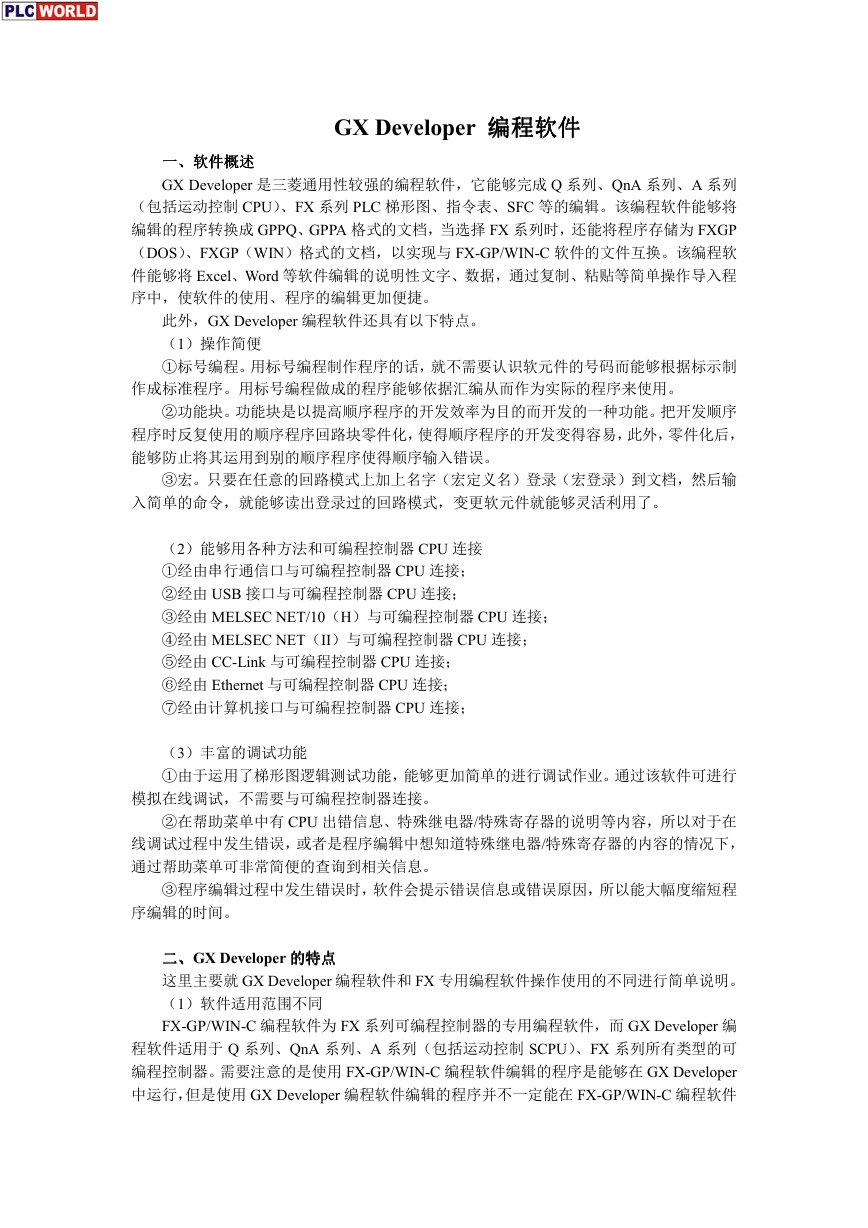 GX Developer 编程软件使用说明.pdf
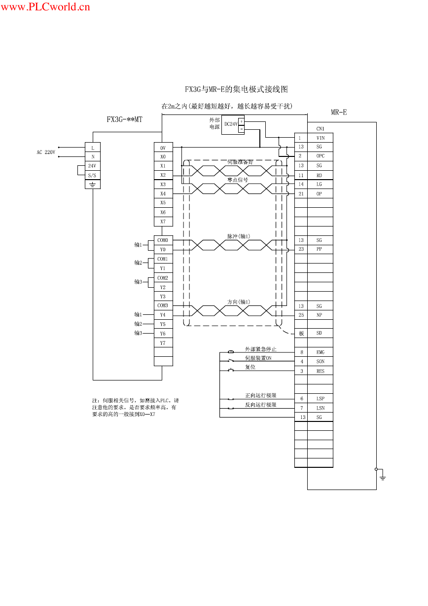 MR-E伺服与FX3G接线图.pdf
 ATK-NEO-6M GPS模块常见问题汇总_201400721.pdf
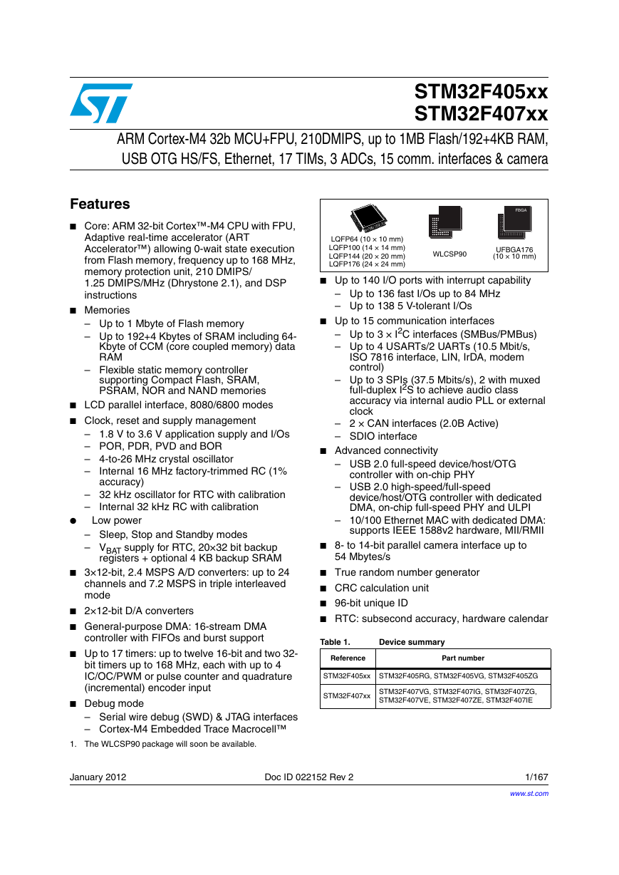 STM32F407ZGT6(芯片资料).pdf
 FM1715编程指南.pdf
 Profibus教程-7.PROFIBUS-FMS.pdf