PROFINET
System Description
n
o
i
t
a
c
i
l
p
p
A
d
n
a
y
g
o
o
n
h
c
e
T
l
Open Solutions for the World of Automation
�
�
Introduction
The ever-shorter innovation cycles for
new products makes the continuous
evolution of automation technology
necessary. The use of fieldbus tech-
nology has been a significant innova-
tion in the past few years. It enabled
the migration of centralized automati-
on systems to distributed automation
systems. PROFIBUS, as a global mar-
ket leader, has set the benchmarks for
20 years.
In today‘s automation technology, mo-
reover, Ethernet and information tech-
nology (IT) is increasingly calling the
shots with established standards like
TCP/IP and XML. The integration of
information technology into automa-
tion is opening up opportunities for
significantly improved communication
between automation systems, far-ran-
ging configurations and diagnostics,
and network-wide service functions.
These functions have been integral
components of PROFINET from the
outset.
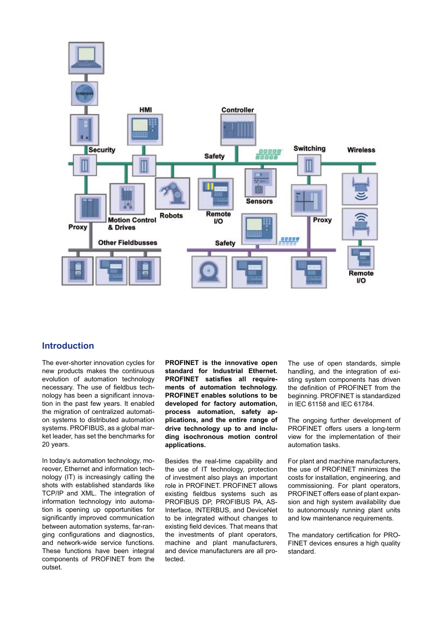
PROFINET is the innovative open
standard for Industrial Ethernet.
PROFINET satisfies all require-
ments of automation technology.
PROFINET enables solutions to be
developed for factory automation,
process automation, safety ap-
plications, and the entire range of
drive technology up to and inclu-
ding isochronous motion control
applications.
Besides the real-time capability and
the use of IT technology, protection
of investment also plays an important
role in PROFINET. PROFINET allows
existing fieldbus systems such as
PROFIBUS DP, PROFIBUS PA, AS-
Interface, INTERBUS, and DeviceNet
to be integrated without changes to
existing field devices. That means that
the investments of plant operators,
machine and plant manufacturers,
and device manufacturers are all pro-
tected.
The use of open standards, simple
handling, and the integration of exi-
sting system components has driven
the definition of PROFINET from the
beginning. PROFINET is standardized
in IEC 61158 and IEC 61784.
The ongoing further development of
PROFINET offers users a long-term
view for the implementation of their
automation tasks.
For plant and machine manufacturers,
the use of PROFINET minimizes the
costs for installation, engineering, and
commissioning. For plant operators,
PROFINET offers ease of plant expan-
sion and high system availability due
to autonomously running plant units
and low maintenance requirements.
The mandatory certification for PRO-
FINET devices ensures a high quality
standard.
�
Contents
1. PROFINET at a Glance ...................................... 3
1.1 PROFINET IO Highlights ...................................... 3
1.2 Standardization ..................................................... 4
1.3 Scope of application of PROFINET ...................... 4
1.4 Perspectives on PROFINET ................................. 4
1.5 Component model (PROFINET CBA) .................. 5
1.6 Distributed I/O (PROFINET IO) ............................ 5
1.7 PROFINET and real-time ...................................... 5
1.8 PROFINET and isochronous mode ...................... 5
1.9 Device classes of PROFINET IO .......................... 5
1.10 Addressing in PROFINET IO ................................ 6
2. PROFINET IO Basics .......................................... 7
2.1 Device model ........................................................ 7
2.2 Application process identifier (API) ....................... 8
2.3 Communication in PROFINET IO ......................... 8
2.4 Principles of real-time communication
in PROFINET IO ................................................... 9
2.5 Real-time classes in PROFINET IO ...................... 9
2.6 Cyclic data traffic ................................................. 10
2.7 Acyclic data traffic ................................................ 10
2.8 Multicast Communication Relation (MCR) ........... 10
2.9 Event-oriented data traffic.................................... 10
3. Diagnostics Concept of PROFINET IO ............. 11
3.1 Overview of the structure of an alarm message .. 11
3.2 Diagnostics in PROFINET ................................... 11
3.3 Monitoring functions in IO-Controller and
IO-Device ............................................................. 11
4. Mode of Operation of PROFINET IO ................. 12
5. System Power-up............................................... 13
5.1 Application and communication relations ............ 13
5.2 Neighborhood detection....................................... 13
5.3 Topology detection ............................................... 14
5.4 Application example for LLDP ............................. 14
5.5 Communication during connection
5.6 Optimized connection establishment
(‚Fast Start Up‘) .................................................... 16
6.
IRT Communication in PROFINET IO ............... 17
6.1 Definition of an IRT domain ................................. 18
6.2 Clock synchronization for IRT communication ..... 18
6.3 Flexible RT_CLASS_ 2 communication .............. 18
6.4 RT_CLASS_3 communication ............................. 19
6.5 System power-up with IRT ................................... 19
6.6 Tips for communication ........................................ 20
6.7 Mixed operation of synchronized and
unsynchronized applications................................ 20
7. PROFINET IO Controller .................................... 21
7.1 Parameter server ................................................. 21
8. Device Description (GSD file) ........................... 24
9.
I&M Functions (Identification & Maintenance) 24
10. Redundancy ....................................................... 25
10.1 Media Redundancy Protocol (MRP) .................... 25
10.2 Media redundancy for RT frames (MRRT)........... 26
10.3 Media redundancy for RT_CLASS_3 frames
establishment and parameterization .................... 15
(MRPD) ................................................................ 26
model ................................................................... 33
component ........................................................... 32
11. Conformance Classes (CC) .............................. 27
12. Application Profiles for PROFINET IO ............. 28
13. PROFINET for PA ............................................... 29
14. Tool Calling Interface (TCI) ............................... 30
15. PROFINET CBA .................................................. 31
15.1 Technological modules in a plant ......................... 31
15.2 Technological module and PROFINET
15.3 PROFINET engineering in the component
model ................................................................... 32
15.4 Downloading to the field devices ......................... 33
15.5 Real-time communication in the component
15.6 Device description for the component model
(PCD) ................................................................... 33
15.7 Software stack for the component model ............ 34
15.8 PROFINET CBA and PROFINET IO ................... 34
Integration of Fieldbus Systems ...................... 36
16.
16.1
Integration via proxy ............................................ 36
16.2 PROFIBUS and other fieldbus systems............... 36
17. Web Integration .................................................. 37
17.1 Security ................................................................ 37
17.2 Segmentation....................................................... 38
17.3 Network management.......................................... 38
17.4
IP management ................................................... 38
17.5 Diagnostics management .................................... 38
18. PROFINET and MES .......................................... 39
18.1 Operations in MES............................................... 39
18.2 Maintenance state ............................................... 39
18.3
Identification......................................................... 39
19. Network Installation ........................................... 40
19.1 PROFINET component approach ........................ 40
19.2 Network topologies .............................................. 40
19.3 Environmental classes ......................................... 41
19.4 PROFINET cabling .............................................. 41
19.5 Plug connectors for data ...................................... 41
19.6 Data cables .......................................................... 41
19.7 Plug connectors ................................................... 42
19.8 Network components ........................................... 42
19.9 PROFINET installation ......................................... 42
19.10 Industrial Wireless ............................................... 42
20. PROFINET IO Technology and Certification ... 43
20.1 Technology support.............................................. 43
20.2 Certification test ................................................... 43
21. PI – the Organization ......................................... 45
21.1 Duties................................................................... 45
21.2 Membership ......................................................... 45
21.3 Organization for technology development ........... 45
21.4 Technical support ................................................. 45
21.5 Documentation..................................................... 46
21.6 Web site ............................................................... 46
22. Glossary ............................................................. 47
2
PROFINET Technology and Application, Version April 2009
�
Plant topology
Visualization of the plant topology
in conjunction with informative dia-
gnostics is integrated in PROFINET.
Plant diagnostics
PROFINET supports convenient plant
diagnostics through a combination of
basic services available as standard
features in the higher-level controller
.
Isochronous data transmission
With PROFINET, deterministic and iso-
chronous transmission of time-critical
process data is possible within a pe-
riod of a few hundred µs. PROFINET
requires this deterministic communi-
cation, for example, for high-accuracy
closed-loop control tasks.
Redundancy concept
PROFINET offers a scalable redun-
dancy concept, which guarantees
smooth changeover from one commu-
nication path to the other in the event
of a fault. The redundancy concept
defined in PROFINET increases the
plant availability significantly.
Device replacement without
ES tool
Failure of a PROFINET device is de-
tected and signaled automatically. No
special knowledge is required to re-
place the device. Any replacement de-
vice in the warehouse can be installed
in the automation system. Addressing
as well as loading of required para-
meters is carried out automatically.
Devices having an incorrect degree of
expansion are detected automatically
during power-up.
Engineering
Through support of the Tool Calling
Interface (TCI), any field device ma-
nufacturer can interact with any TCI-
capable engineering system (ES) and
communicate with „its“ field devices
(Device Tool) from the ES for purpo-
ses of assigning parameters and per-
forming diagnostics.
individual parameters
Saving of
(iPar server)
Parameters determined on a plant-
specific basis are saved and loaded
autonomously. The iPar server allows
vendor-neutral loading (e.g., via TCI)
of
individually-assigned parameters
optimized for the specific plant as well
as automatic archiving on a parameter
server. Downloading also occurs auto-
matically during device replacement.
1. PROFINET at a Glance
PROFINET is the automation stan-
dard of PROFIBUS&PROFINET In-
ternational (PI). PROFINET is 100%
Ethernet-compatible as defined
in
IEEE Standards. With PROFINET, the
following minimum data communica-
tion requirements are automatically
established:
• 100 Mbps data communication with
copper or fiber optic transmission
(100 Base TX and 100 Base FX)
• Full duplex transmission
• Switched Ethernet
• Autonegotiation
transmission parameters)
(negotiating of
• Autocrossover (sending and recei-
ving
the
switch)
lines are crossed
in
• Wireless communication (WLAN
and Bluetooth)
PROFINET uses UDP/IP as
the
higher level protocol for demand-
oriented data exchange. UDP (User
Datagram Protocol) contains the non-
secure, connectionless broadcast
communication in conjunction with IP.
In parallel to UDP/IP communication,
cyclic data exchange in PROFINET
is based on a scalable real-time con-
cept.
1.1 PROFINET IO Highlights
The four key functions of PROFINET
are:
• Performance: automation in real-
time
• Safety: safety-related communica-
tion with PROFIsafe
• Diagnostics: high plant availability
due to fast commissioning and
efficient troubleshooting
•
Investment protection: seamless
integration of fieldbus systems
In addition, PROFINET offers a series
of special functions.
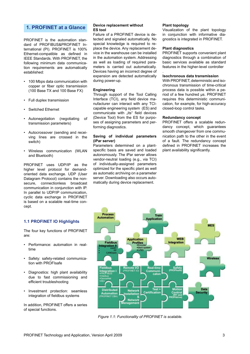
Figure 1.1: Functionality of PROFINET is scalable.
PROFINET Technology and Application, Version April 2009
3
�
Very simple device replacement
The integrated neighborhood detec-
tion functionality enables PROFINET
field devices to identify their neigh-
bors. Thus, in the event of a problem,
field devices can be replaced without
additional tools or prior knowledge.
This information can be used to repre-
sent the plant topology in a very easy
to understand graphic display.
1.2 Standardization
PROFINET IO has been incorporated
in the current edition of IEC 61158.
IEC 61784 describes the subsets of
the services specified in IEC 61158
that are to be applied for PROFINET.
The PROFINET concept was defined
in close cooperation with end users.
Additions to the standard Ethernet
protocol as defined in IEEE 802 were
made by PI only in cases where the
existing standard could not meet the
requirements in a satisfactory man-
ner.
1.3 Scope of application of
PROFINET
PROFINET satisfies all requirements
of automation technology. The many
years of experience with PROFIBUS
and the widespread use of Industrial
Ethernet have been rolled into PRO-
FINET.
The use of IT standards, simple hand-
ling, and the integration of existing
system components have driven the
definition of PROFINET from the be-
ginning. The figure below summarizes
the functionality currently provided by
PROFINET.
The ongoing further development of
PROFINET offers users a long-term
view for the implementation of their
automation tasks.
For plant and machine manufactu-
rers, the use of PROFINET minimizes
the costs for installation, engineering,
and commissioning.
The plant operator benefits from the
ease of plant expansion and high avai-
lability due to autonomously running
plant units.
Establishment of the proven certifica-
tion process ensures a high standard
of quality for PROFINET products.
Use of the user profiles defined up to
now means that PROFINET can be
used in virtually every sector of auto-
mation engineering. PROFINET pro-
files for the process industry and for
train applications are currently under
development.
1.4 Perspectives on
PROFINET
The PROFINET concept is a modular
concept that allows the user to chose
the functionality he requires.
functionality differs mainly
The
in
terms of the type of data exchange.
This distinction is necessary to satis-
fy the very stringent requirements for
data transmission speed that exist for
some applications. Figure 1.2 shows
the relationship between the PROFI-
NET CBA and PROFINET IO perspec-
tives. Both communication paths can
be used in parallel.
PROFINET CBA is suitable for com-
ponent-based machine-to-machine
communication via TCP/IP and for
real-time communication to meet real-
time requirements in modular plant
manufacturing. It enables a simple mo-
dular design of plants and production
lines based on distributed intelligence
using graphics-based configuration
of communication between intelligent
modules.
PROFINET IO describes an I/O data
view on distributed I/O. PROFINET IO
features real-time (RT) communica-
tion and isochronous real-time (IRT)
communication with the distributed
I/O. The designations RT and IRT are
used solely to describe the real-time
properties of communication.
PROFINET CBA and PROFINET IO
can be operated separately and in
combination such that a PROFINET
IO unit appears in the plant view as a
PROFINET CBA plant.
Figure 1.2: PROFINET perspectives.
4
PROFINET Technology and Application, Version April 2009
�
1.5 Component model
(PROFINET CBA)
This variant is defined in PROFINET
CBA (Component Based Automation).
Its strength is revealed in communi-
cation between Programmable Logic
Controllers (PLC). The basic idea
behind CBA is that whole automation
systems can be often be grouped into
autonomously operating and, thus,
very clearly arranged units. The struc-
ture and functionality can be repeated
in identical, or slightly modified, form
in multiple plants. These so-called
PROFINET components are generally
controlled by an easily identified set of
input signals. Within the component,
a control program written by the user
executes the required functionality of
the component and sends the corre-
sponding output signals to another
controller. The engineering associated
with this is vendor-neutral. Communi-
cation in a component-based system
is configured rather than programmed.
The communication with PROFINET
CBA (without real-time) is suitable for
bus cycle times of approximately 50 to
100 ms. Data cycles on the order of
milliseconds are possible in the paral-
lel RT channel - same as in PROFI-
NET IO.
1.6 Distributed I/O
(PROFINET IO)
PROFINET IO is used to connect dis-
tributed I/O for fast data exchange.
The scalable real-time concept is the
basis for this.
PROFINET IO describes the overall
data exchange between controllers
(devices with master functionality ac-
cording to PROFIBUS) and devices
(devices with slave functionality) as
well as the parameterization and di-
agnostic options. A device developer
can implement PROFINET IO with
any commercially available Ethernet
controller. The bus cycle times for the
data exchange are in the milliseconds
range. Configuring an PROFINET IO
system has the same look and feel as
in PROFIBUS. The real-time concept
is included in PROFINET IO without
exception.
1.7 PROFINET and real-time
Within PROFINET IO, process data
and alarms are always transmitted in
real time. Real-Time for PROFINET
(RT) is based on the definitions of
IEEE and IEC for high-performance
data exchange of I/O data. RT com-
munication constitutes the basis for
data exchange in PROFINET IO.
Real-time data are handled with high-
er priority compared to TCP(UDP)/IP
data. This method of data exchange
allows bus cycle times in the range
of a few hundred milliseconds to be
achieved.
1.8 PROFINET and iso-
chronous mode
Isochronous data exchange with
PROFINET is defined in the Isochro-
nous-Real-Time (IRT) concept. Data
exchange cycles are normally in the
range of a few hundred microseconds
to 1 millisecond. Isochronous real-
time communication differs from real-
time communication mainly in its iso-
chronous behavior, meaning that the
bus cycles are started with maximum
precision. The start of a bus cycle can
deviate by a maximum of 1 µs. IRT is
required in motion control applications
(positioning operations), for example.
1.9 Device classes of
PROFINET IO
PROFINET follows the Provider/Con-
sumer model for data exchange. The
provider (usually the field device at the
process level) provides process data
to a consumer (normally a PLC with
a processing program). In principle, a
PROFINET IO field device can contain
any arrangement of functions (provi-
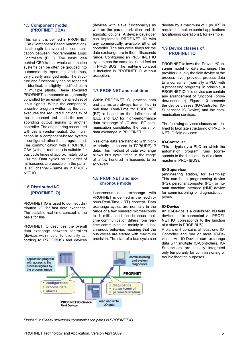
der/consumer). Figure 1.3 presents
the device classes (IO-Controller, IO-
Supervisor, IO-Device) and the com-
munication services.
The following devices classes are de-
fined to facilitate structuring of PROFI-
NET IO field devices:
runs
IO-Controller
This is typically a PLC on which the
automation program
(corre-
sponds to the functionality of a class 1
master in PROFIBUS).
IO-Supervisor
(engineering station, for example):
This can be a programming device
(PG), personal computer (PC), or hu-
man machine interface (HMI) device
for commissioning or diagnostic pur-
poses.
IO-Device
An IO-Device is a distributed I/O field
device that is connected via PROFI-
NET IO (corresponds to the function
of a slave in PROFIBUS).
A plant unit contains at least one IO-
Controller and one or more IO-De-
vices. An IO-Device can exchange
data with multiple IO-Controllers. IO-
Supervisors are usually
integrated
only temporarily for commissioning or
troubleshooting purposes.
Figure 1.3: Clearly structured communication paths in PROFINET IO.
PROFINET Technology and Application, Version April 2009
5
�
Following address resolution, the sy-
stem powers up and parameters are
transmitted to the IO-Devices. The
system is then available for productive
data traffic.
1.10 Addressing in
PROFINET IO
PROFINET
IO field devices are
addressed using MAC addresses and
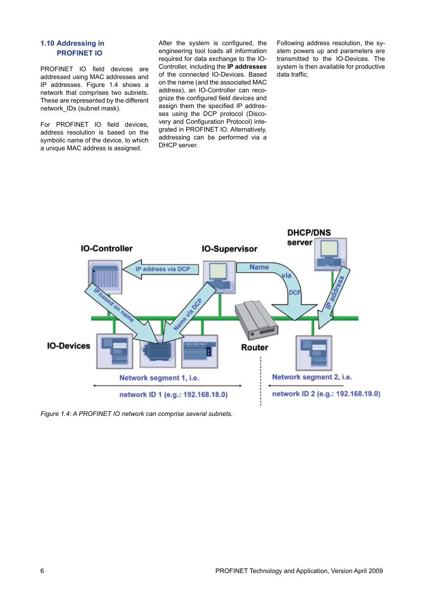
IP addresses. Figure 1.4 shows a
network that comprises two subnets.
These are represented by the different
network_IDs (subnet mask).
For PROFINET
IO field devices,
address resolution is based on the
symbolic name of the device, to which
a unique MAC address is assigned.
After the system is configured, the
engineering tool loads all information
required for data exchange to the IO-
Controller, including the IP addresses
of the connected IO-Devices. Based
on the name (and the associated MAC
address), an IO-Controller can reco-
gnize the configured field devices and
assign them the specified IP addres-
ses using the DCP protocol (Disco-
very and Configuration Protocol) inte-
grated in PROFINET IO. Alternatively,
addressing can be performed via a
DHCP server.
Figure 1.4: A PROFINET IO network can comprise several subnets.
6
PROFINET Technology and Application, Version April 2009
�
