AN 073120
mifare Ultralight Features and Hints
Rev. 2.0 — 18 December 2006
Application note
Document information
Info
Content
Keywords
Abstract
Multiple ticketing, secured data storage, implementation hints
This document presents features and hints for a secured and optimized
application development using mifare® Ultralight cards.
�
NXP Semiconductors
Revision history
Rev
Date
Description
AN 073120
mifare Ultralight Features and Hints
2.0
1.0
18.12.2006
15.05.2002
Security features (section 2.2) and example (annex 6.3) added
First release
Contact information
For additional information, please visit: http://www.nxp.com
For sales office addresses, please send an email to: salesaddresses@nxp.com
Rev. 2.0 — 18 December 2006
© NXP B.V. 2006. All rights reserved.
2 of 21
Application note
�
NXP Semiconductors
1.
Introduction
AN 073120
mifare Ultralight Features and Hints
1.1 Purpose and Scope
This application note is intended to describe the features of the mifare® Ultralight
MF0ICU1, and the comparison to the mifare® Classic MF1ICS50.
It addresses some security mechanisms which may be used to protect the data stored in
the card and demonstrates the implementation of mifare® Ultralight into an existing
mifare® Classic application and shows the necessary modification over the existing
mifare® reader environment. The changes apply to all relevant Philips mifare® readers.
1.2 How to use this document
Ultralight.
This document contains a collection of hints and features that could be of interest for
those, who plan to use the mifare®
None of this information is intended to replace any of the relevant datasheets or design
guides.
1.3 Reference documents
1. [M028630] mifare® Ultralight, Contact-less Single-trip Ticket IC MF0 IC U1, Functional
Specification.
2. [M011731] mifare®, (Card) Coil Design Guide.
3. [sl070010] Temperature Management, Inlet Design.
4. [M057432] MIFARE® MF RC530 ISO14443A reader IC.
5. [M056633] MIFARE® MF RC531; ISO 14443 Reader IC.
6. [MC073933] MIFARE® and I Code CL RC632 Multiple protocol contact less reader IC.
7. [ISO/IEC 14443-3] Identification cards- Contactless integrated circuit(s) cards-
proximity cards- Part 3: Initialization and anticollision.
8. [FIPS46-3] Data Encryption Standard.
9. [ISO/IEC 9797-1] Information technology Security techniques Message Authentication
Codes.
Application note
Rev. 2.0 — 18 December 2006
© NXP B.V. 2006. All rights reserved.
3 of 21
�
NXP Semiconductors
2. Mifare® Ultralight application hints
AN 073120
mifare Ultralight Features and Hints
2.1 Memory features
In addition to the user memory area the mifare® Ultralight offers the features of an OTP1
area and lock bytes to lock the OTP and user area. The usages of LOCK bits are
described in [M028630].
A mifare® Ultralight dedicated 4-byte WRITE-command provides a high transaction
speed. All the add-on features are dedicated to support special application functionality
e.g. ticketing.
2.1.1 Using OTP memory for multiple ticketing
Initialize: Write “FFFFFFF0 hex”
The 4 OTP bytes, which are pre-set to “0” at the delivery, can be set to “1” only once.
This gives the possibility to interpret them as an irreversible counter. Therefore, the
number of “1” bits in Page 3 can be considered as counter value. This counter can be
incremented by changing a bit from “0” to”1”. The counter cannot be decremented due to
a “1” bit of Page 3 cannot be cleared. In this case this 4-byte offers a number of 32 states
that could be used to allow a certain number of passing turn-styles.
Example:
An example of a four rides ticket is shown in figure 1. For this application a ticket issuing
the OTP memory of the mifare® Ultralight has to be pre-set to “FFFFFFF0hex”.
Page 3:
Byte 12
Page 3:
Byte 12
1111
Page 3:
Byte 12
Page 3:
Byte 12
Page 3:
Byte 12
First use
Last use
2nd use
14
1111
15
1111
0111
13
1111
1111
15
1111
13
1111
1111
14
1111
15
1111
0011
14
1111
14
1111
1111
15
1111
13
1111
1111
13
1111
1111
3rd use
1111
0001
1111
1111
1111
1111
1111
1111
13
1111
1111
15
1111
1111
1111
1111
1111
0000
1111
1111
14
1111
1111
Figure 1: Example of a four rides ticket
Application note
1 One Time Programming
Rev. 2.0 — 18 December 2006
© NXP B.V. 2006. All rights reserved.
4 of 21
�
NXP Semiconductors
AN 073120
mifare Ultralight Features and Hints
For every access, the 4-byte OTP (page 3) has to be checked and updated (as shown in
Figure 2) to ensure the validity of the tickets. Using the same command flow the counter
might be extended to a number of 31 times just by changing the initial memory content.
E.g. “FFFFFC00hex” or “FC00FC00hex” might be used for a 10 times counter initial
value, or “FFF00000hex” for a 20 times counter initial value, which has to be written into
the OTP memory while issuing the ticket.
Application rotates left Page 3 by one bit
Write new value back into page 3
Grant Access
=“FFFFFFFFhex”?
Refuse entry → new ticket
yes
Read Page 3
no
Figure 2: Ticket Counter Command flow
Remark:
With the initial value “00000000hex” for 32 times counter, the rotate left at the very first
access check after selling the ticket has to be exchanged into another initial WRITE
command.
Application note
Rev. 2.0 — 18 December 2006
© NXP B.V. 2006. All rights reserved.
5 of 21
�
NXP Semiconductors
AN 073120
mifare Ultralight Features and Hints
2.1.2 Transaction Speed
Although the mifare® Ultralight offers the 16-byte Compatibility Write command to be
compatible with the mifare® Classic environment, the use of the 4 byte Write command is
recommended,
transaction. The Write saves
approximately 20% of the transaction time2 compared to the Compatibility Write, as can
be seen in Table 1.
the application requires a
fast
if
Command
REQA
Anticollision level 1 + 2 & Select
Read
Write
Compatibility Write
Halt
∑ (approximately)
4 pages
0.4 ms
3.7 ms
2.0 ms
12 pages
0.4 ms
3.7 ms
6.0 ms
18.7 ms
56 ms
24.0 ms
72 ms
0.5 ms
0.5 ms
25.3 ms
30.6 ms
66.6 ms
82.6 ms
The transaction time2 as shown in Table 1 counts the time needed for
Table 1: Transaction time
the communication from the reader to the mifare® Ultralight,
the response time of the mifare® Ultralight and
the communication from the mifare® Ultralight back to the reader.
•
•
•
2 This doesn’t include the time requires the host computer for the application itself (e.g. calculating &
checking ticket values, displaying results, opening gates, etc.).
Application note
Rev. 2.0 — 18 December 2006
© NXP B.V. 2006. All rights reserved.
6 of 21
�
NXP Semiconductors
AN 073120
mifare Ultralight Features and Hints
2.2 Proposed Security Mechanism
Mifare® Ultralight has been designed to support the faster application with the cheapest
solution. Therefore it does not address any security feature except the unique identity
(UID). From the application point of view this means, no authentication has to be
performed and no key is needed. Performing a mifare® authentication generates an error,
and the mifare® Ultralight goes back to the Idle (or Halt) state.
But if requires, smarter secured application using mifare® Ultralight can be created using
an intelligent reader with the respective application software. A lot of cryptographic
technologies are available to assist you. One successfully implemented approach is
demonstrated in the following sections. This approach uses a 16-byte Master key (Mk),
which is used to add the confidentiality and integrity of the storage data.
2.2.1 Confidentiality of stored Data
As the mifare® Ultralight pages can be read without any authentication, anyone can read
the pages using any standard reader. But if the stored data is encrypted with a secured
key then these are just some bytes to one who does not have the secret key and
information regarding the encryption method. Therefore by storing the encrypted data in
mifare® Ultralight memory, one can add the confidentiality to the data itself.
As an example a 3-DES [FIPS46-3] may be used for this encryption.
Data
stored
=
f
(
key
,
data
origin
)UID
,
7-byte UID of the mifare® Ultralight has to be incorporated in the security system
to confirm the uniqueness of the tickets and a 16-byte Master Key (Mk) has to be
defined by the application provider. To decrease the threat on the Master key
(Mk), for each card, a Card key (Ck) is derived from the Master Key (Mk) using
the well known key diversification. The steps to be followed are:
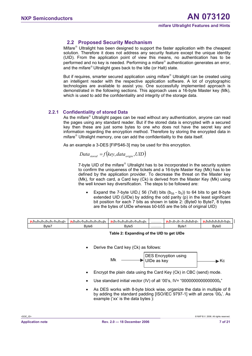
• Expand the 7-byte UID,( 56 (7x8) bits (b55 - b0)) to 64 bits to get 8-byte
extended UID (UIDe) by adding the odd parity (p) in the least significant
bit position for each 7 bits as shown in table 2: (Byte0 to Byte7, 8 bytes
are the bytes of UIDe whereas b0-b55 are the bits of original UID)
p7b55b54b53b52b51b50b49p7 p6b48b47b46b45b44b43b42p6 p5b41b40b39b38b37b36b35p5 ………
………
Byte7
Byte6
Byte5
Byte1
Table 2: Expanding of the UID to get UIDe
p1b13b12b11b10b9b8b7p1 p0b6b5b4b3b2b1b0p0
Byte0
• Derive the Card key (Ck) as follows:
Mk
DES Encryption using
UIDe as key
Kc
• Encrypt the plain data using the Card Key (Ck) in CBC (send) mode.
• Use standard initial vector (IV) of all ‘00’s, IV= “0000000000000000h”
• As DES works with 8-byte block wise, organize the data in multiple of 8
by adding the standard padding [ISO/IEC 9797-1] with all zeros ‘00h’. As
example (‘xx’ is the data bytes ):
Rev. 2.0 — 18 December 2006
© NXP B.V. 2006. All rights reserved.
7 of 21
Application note
�
NXP Semiconductors
AN 073120
mifare Ultralight Features and Hints
2 padding bytes: xx xx xx xx xx xx 00 00
7 padding bytes: xx 00 00 00 00 00 00 00
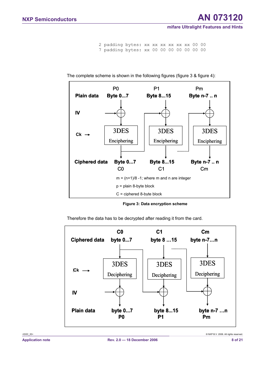
The complete scheme is shown in the following figures (figure 3 & figure 4):
Plain data
Plain data
IV = f(UID)
IV = f(UID)
Ck
MK
MK
P0
P0
P1 Pm
P1 Pm
Byte 0...7 Byte 8...15 Byte n-7 .. n
Byte 0...7 Byte 8...15 Byte n-7 .. n
3DES
3DES
Enciphering
Enciphering
3DES
3DES
Enciphering
Enciphering
3DES
3DES
Enciphering
Enciphering
Ciphered data Byte 0...7 Byte 8...15 Byte n-7 .. n
Ciphered data Byte 0...7 Byte 8...15 Byte n-7 .. n
C0
C0
C1 Cm
C1 Cm
m = (n+1)/8 -1; where m and n are integer
p = plain 8-byte block
C = ciphered 8-byte block
Figure 3: Data encryption scheme
C1 Cm
C1 Cm
byte 8 …15
byte 8 …15
byte n-7…n
byte n-7…n
C0
C0
Ciphered data
Ciphered data
byte 0...7
byte 0...7
Therefore the data has to be decrypted after reading it from the card.
3DES
3DES
Deciphering
Deciphering
3DES
3DES
Deciphering
Deciphering
IV = f(UID)
IV = f(UID)
MK
MK
Ck
P0
P0
P1 Pm
P1 Pm
3DES
3DES
Deciphering
Deciphering
Plain data
Plain data
byte 0...7 byte 8...15 byte n-7 …n
byte 0...7 byte 8...15 byte n-7 …n
Application note
Rev. 2.0 — 18 December 2006
© NXP B.V. 2006. All rights reserved.
8 of 21
�


