20-Mar-2000
CANopen
CANopen
high-level protocol for CAN-bus
H. Boterenbrood
NIKHEF, Amsterdam
March 20, 2000
Contents
1
INTRODUCTION ......................................................................................................................................... 2
2 CAL................................................................................................................................................................. 2
3.1
3.2
3.3
3.4
3.5
3.6
3 CANOPEN ..................................................................................................................................................... 3
CANOPEN OBJECT DICTIONARY .............................................................................................................. 3
CANOPEN COMMUNICATION.................................................................................................................... 5
CANOPEN PREDEFINED CONNECTION SET............................................................................................... 7
CANOPEN IDENTIFIER DISTRIBUTION ....................................................................................................... 8
CANOPEN BOOT-UP PROCESS ................................................................................................................... 9
DETAILS OF CANOPEN MESSAGE SYNTAX.............................................................................................. 10
NMT Module Control ................................................................................................................... 10
3.6.1
NMT Node Guarding.................................................................................................................... 10
3.6.2
NMT Boot-up ................................................................................................................................ 10
3.6.3
PDO............................................................................................................................................... 11
3.6.4
SDO ............................................................................................................................................... 11
3.6.5
3.6.6
Emergency Object ......................................................................................................................... 14
SUMMARY.................................................................................................................................................. 16
4
5 EXAMPLE OF A CANOPEN OBJECT DICTIONARY FOR DEVICES WITH CS5525 ADCS....... 17
INTRODUCTION....................................................................................................................................... 17
ADC READ-OUT..................................................................................................................................... 17
ADC CONFIGURATION AND CALIBRATION............................................................................................. 18
THE OBJECT DICTIONARY ...................................................................................................................... 18
EMERGENCY OBJECTS ............................................................................................................................ 22
REFERENCES .................................................................................................................................................... 23
5.1
5.2
5.3
5.4
5.5
1
�
CANopen
Version History
Version Date
1998
1999
1.x
2.0
15-Mar-2000
Comments
First draft versions
Change of title; change in chapter numbering; addition of CAN message syntax
details
Corrected error in table 7 and 8 captions
Several additions in accordance with CiA DS301 CANopen Communication Pro-
file Version 4.0 (update from 3.0)
Layer
CAN Controller
Device Profile
CiA DSP-xxx
Device Profile
CiA DSP-401
Device Profile
CiA DSP-404
Communication Profile CiA DS-301
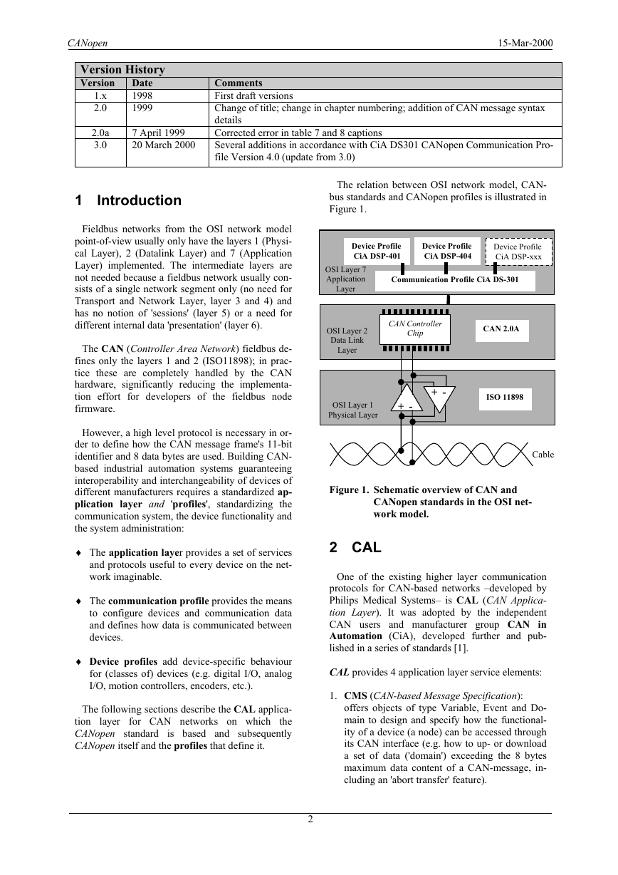
The relation between OSI network model, CAN-
bus standards and CANopen profiles is illustrated in
Figure 1.
OSI Layer 7
Application
OSI Layer 2
Data Link
OSI Layer 1
Physical Layer
Figure 1. Schematic overview of CAN and
ISO 11898
CAN 2.0A
+ -
Layer
Chip
+ -
CANopen standards in the OSI net-
work model.
Cable
2 CAL
One of the existing higher layer communication
protocols for CAN-based networks –developed by
Philips Medical Systems– is CAL (CAN Applica-
tion Layer). It was adopted by the independent
CAN users and manufacturer group CAN in
Automation (CiA), developed further and pub-
lished in a series of standards [1].
CAL provides 4 application layer service elements:
1. CMS (CAN-based Message Specification):
offers objects of type Variable, Event and Do-
main to design and specify how the functional-
ity of a device (a node) can be accessed through
its CAN interface (e.g. how to up- or download
a set of data ('domain') exceeding the 8 bytes
maximum data content of a CAN-message, in-
cluding an 'abort transfer' feature).
2.0a
3.0
7 April 1999
20 March 2000
Introduction
1
Fieldbus networks from the OSI network model
point-of-view usually only have the layers 1 (Physi-
cal Layer), 2 (Datalink Layer) and 7 (Application
Layer) implemented. The intermediate layers are
not needed because a fieldbus network usually con-
sists of a single network segment only (no need for
Transport and Network Layer, layer 3 and 4) and
has no notion of 'sessions' (layer 5) or a need for
different internal data 'presentation' (layer 6).
The CAN (Controller Area Network) fieldbus de-
fines only the layers 1 and 2 (ISO11898); in prac-
tice these are completely handled by the CAN
hardware, significantly reducing the implementa-
tion effort for developers of the fieldbus node
firmware.
However, a high level protocol is necessary in or-
der to define how the CAN message frame's 11-bit
identifier and 8 data bytes are used. Building CAN-
based industrial automation systems guaranteeing
interoperability and interchangeability of devices of
different manufacturers requires a standardized ap-
plication layer and 'profiles', standardizing the
communication system, the device functionality and
the system administration:
♦ The application layer provides a set of services
and protocols useful to every device on the net-
work imaginable.
♦ The communication profile provides the means
to configure devices and communication data
and defines how data is communicated between
devices.
♦ Device profiles add device-specific behaviour
for (classes of) devices (e.g. digital I/O, analog
I/O, motion controllers, encoders, etc.).
layer for CAN networks on which
The following sections describe the CAL applica-
the
is based and subsequently
tion
CANopen standard
CANopen itself and the profiles that define it.
2
�
CANopen
CMS derives from MMS (Manufacturing Mes-
sage Specification), which is an OSI application
layer protocol designed for the remote control
and monitoring of industrial devices.
2. NMT (Network ManagemenT):
offers services to support network management,
e.g. to initialize, start or stop nodes, detect node
failures; this service is implemented according
to a master-slave concept (there is one NMT
master).
3. DBT (DistriBuTor):
offers a dynamic distribution of CAN identifiers
(officially called COB-ID, Communication Ob-
ject Identifier) to the nodes on the network; this
service is implemented according to a master-
slave concept (there is one DBT master).
4. LMT (Layer ManagemenT):
offers the ability to change layer parameters e.g.
change the NMT-address of a node,
or change bit-timing and baud-rate of the CAN-
interface.
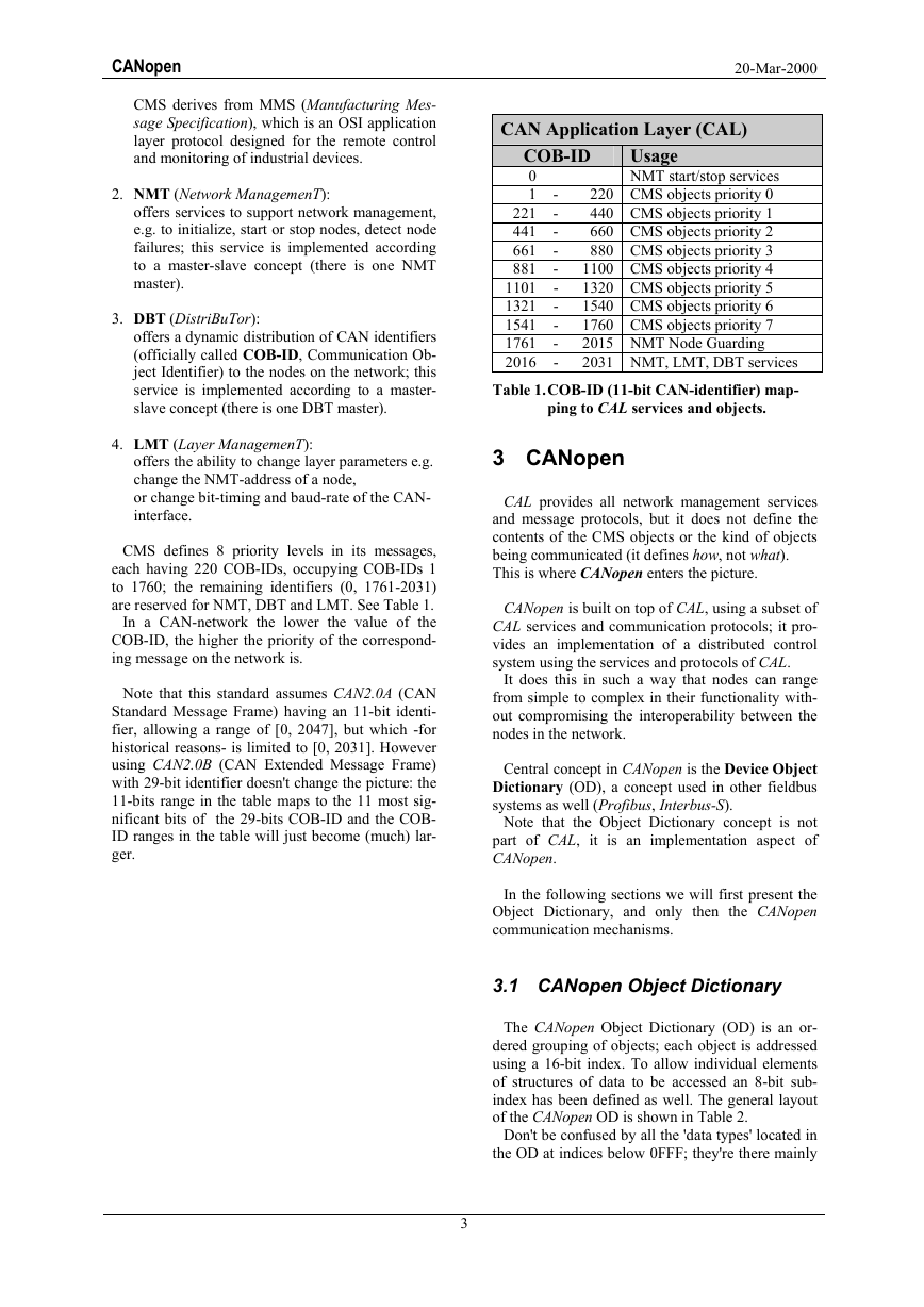
CMS defines 8 priority levels in its messages,
each having 220 COB-IDs, occupying COB-IDs 1
to 1760; the remaining identifiers (0, 1761-2031)
are reserved for NMT, DBT and LMT. See Table 1.
In a CAN-network the lower the value of the
COB-ID, the higher the priority of the correspond-
ing message on the network is.
Note that this standard assumes CAN2.0A (CAN
Standard Message Frame) having an 11-bit identi-
fier, allowing a range of [0, 2047], but which -for
historical reasons- is limited to [0, 2031]. However
using CAN2.0B (CAN Extended Message Frame)
with 29-bit identifier doesn't change the picture: the
11-bits range in the table maps to the 11 most sig-
nificant bits of the 29-bits COB-ID and the COB-
ID ranges in the table will just become (much) lar-
ger.
20-Mar-2000
CAN Application Layer (CAL)
Usage
COB-ID
0
1
221
441
661
881
1101
1321
1541
1761
2016
NMT start/stop services
220 CMS objects priority 0
440 CMS objects priority 1
660 CMS objects priority 2
880 CMS objects priority 3
1100 CMS objects priority 4
1320 CMS objects priority 5
1540 CMS objects priority 6
1760 CMS objects priority 7
2015 NMT Node Guarding
2031 NMT, LMT, DBT services
Table 1. COB-ID (11-bit CAN-identifier) map-
-
-
-
-
-
-
-
-
-
-
ping to CAL services and objects.
3 CANopen
CAL provides all network management services
and message protocols, but it does not define the
contents of the CMS objects or the kind of objects
being communicated (it defines how, not what).
This is where CANopen enters the picture.
CANopen is built on top of CAL, using a subset of
CAL services and communication protocols; it pro-
vides an implementation of a distributed control
system using the services and protocols of CAL.
It does this in such a way that nodes can range
from simple to complex in their functionality with-
out compromising the interoperability between the
nodes in the network.
Central concept in CANopen is the Device Object
Dictionary (OD), a concept used in other fieldbus
systems as well (Profibus, Interbus-S).
Note that the Object Dictionary concept is not
part of CAL, it is an implementation aspect of
CANopen.
In the following sections we will first present the
Object Dictionary, and only then the CANopen
communication mechanisms.
3.1 CANopen Object Dictionary
The CANopen Object Dictionary (OD) is an or-
dered grouping of objects; each object is addressed
using a 16-bit index. To allow individual elements
of structures of data to be accessed an 8-bit sub-
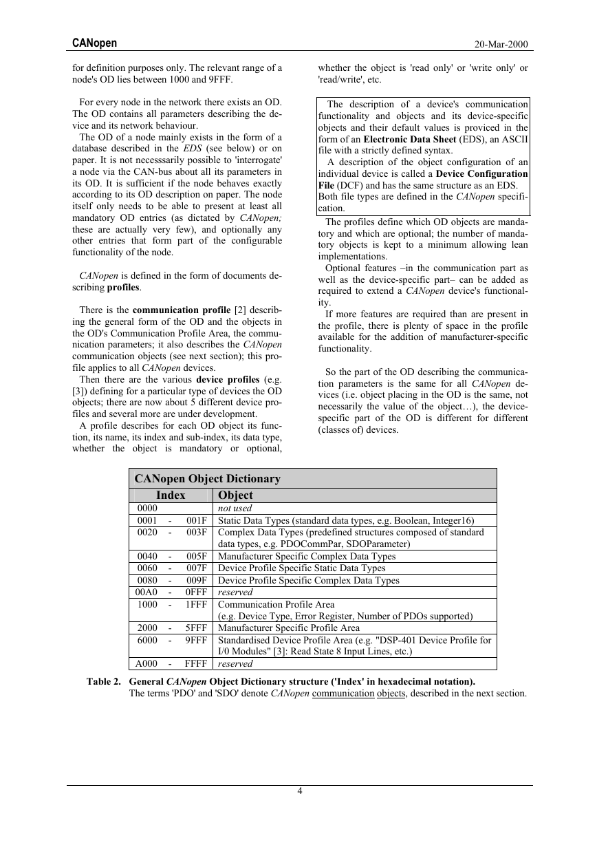
index has been defined as well. The general layout
of the CANopen OD is shown in Table 2.
Don't be confused by all the 'data types' located in
the OD at indices below 0FFF; they're there mainly
3
�
CANopen
for definition purposes only. The relevant range of a
node's OD lies between 1000 and 9FFF.
For every node in the network there exists an OD.
The OD contains all parameters describing the de-
vice and its network behaviour.
The OD of a node mainly exists in the form of a
database described in the EDS (see below) or on
paper. It is not necesssarily possible to 'interrogate'
a node via the CAN-bus about all its parameters in
its OD. It is sufficient if the node behaves exactly
according to its OD description on paper. The node
itself only needs to be able to present at least all
mandatory OD entries (as dictated by CANopen;
these are actually very few), and optionally any
other entries that form part of the configurable
functionality of the node.
CANopen is defined in the form of documents de-
scribing profiles.
There is the communication profile [2] describ-
ing the general form of the OD and the objects in
the OD's Communication Profile Area, the commu-
nication parameters; it also describes the CANopen
communication objects (see next section); this pro-
file applies to all CANopen devices.
Then there are the various device profiles (e.g.
[3]) defining for a particular type of devices the OD
objects; there are now about 5 different device pro-
files and several more are under development.
A profile describes for each OD object its func-
tion, its name, its index and sub-index, its data type,
whether the object is mandatory or optional,
CANopen Object Dictionary
20-Mar-2000
whether the object is 'read only' or 'write only' or
'read/write', etc.
The description of a device's communication
functionality and objects and its device-specific
objects and their default values is proviced in the
form of an Electronic Data Sheet (EDS), an ASCII
file with a strictly defined syntax.
A description of the object configuration of an
individual device is called a Device Configuration
File (DCF) and has the same structure as an EDS.
Both file types are defined in the CANopen specifi-
cation.
The profiles define which OD objects are manda-
tory and which are optional; the number of manda-
tory objects is kept to a minimum allowing lean
implementations.
Optional features –in the communication part as
well as the device-specific part– can be added as
required to extend a CANopen device's functional-
ity.
If more features are required than are present in
the profile, there is plenty of space in the profile
available for the addition of manufacturer-specific
functionality.
So the part of the OD describing the communica-
tion parameters is the same for all CANopen de-
vices (i.e. object placing in the OD is the same, not
necessarily the value of the object…), the device-
specific part of the OD is different for different
(classes of) devices.
Index
Object
not used
001F Static Data Types (standard data types, e.g. Boolean, Integer16)
003F Complex Data Types (predefined structures composed of standard
data types, e.g. PDOCommPar, SDOParameter)
005F Manufacturer Specific Complex Data Types
007F Device Profile Specific Static Data Types
009F Device Profile Specific Complex Data Types
0FFF
1FFF Communication Profile Area
reserved
0000
0001
0020
-
-
0040
0060
0080
00A0
1000
2000
6000
-
-
-
-
-
-
-
(e.g. Device Type, Error Register, Number of PDOs supported)
5FFF Manufacturer Specific Profile Area
9FFF Standardised Device Profile Area (e.g. "DSP-401 Device Profile for
A000
- FFFF
I/0 Modules" [3]: Read State 8 Input Lines, etc.)
reserved
Table 2. General CANopen Object Dictionary structure ('Index' in hexadecimal notation).
The terms 'PDO' and 'SDO' denote CANopen communication objects, described in the next section.
4
�
20-Mar-2000
CANopen
Trans-
Mission
Type
0
1-240
241-251
252
253
254
255
B
O
-
B
-
-
-
Condition to trigger PDO
(B=both needed, O=one or both)
SYNC*
RTR*
Event*
PDO
Transmission
-
-
-
B
O
O
O
B
-
-
-
-
O
O
Sync, acyclic
Sync, cyclic
reserved
Sync, after RTR
Async, after RTR
Async, manufacturer specific event
Async, device profile specific event
*SYNC= SYNC-object received.
*RTR = Remote Transmission Request received (= a 'Remote Frame' CAN-message).
*Event = e.g. 'Change-of-Value' or timer-interrupt.
Table 3. Definition of PDO transmission types in CANopen; for types 1 to 240 the number indicates
the number of SYNC objects between two PDO transmissions.
3.2 CANopen communication
Now that we have presented the concept of the
Object Dictionary we now will look at the messages
that are communicated in CANopen networks, their
content and their function, in other words: the
CANopen communication model (see [2]).
in
NB: be sure to make the distinction between OD
objects (objects
the Object Dictionary) –
characterized by their OD index and sub-index, as
described in the previous section– and communica-
tion objects or messages, characterized by their
COB-ID or CAN-identifier, described in this sec-
tion.
The CANopen communication model defines four
types of messages (communication objects):
1. Administrative message:
Layer management, network management
and identifier distribution services: i.e ini-
tialisation, configuration and supervision of
the network (the
includes
'node/life guarding': see below).
latter aspect
Services and protocols are according to the
LMT, NMT and DBT service elements of
CAL. These services are all based on a Mas-
ter-Slave concept: in a CAN-network there
is only one LMT-, NMT- or DBT-master
and one or more slaves.
2. Service Data Object (SDO):
An SDO provides a client access to entries
(objects) of a device OD (the device is the
server) using the object's OD index and sub-
index, contained in the first few bytes of the
CAN-message.
5
3. Process Data Object (PDO):
An SDO is implemented as a CMS object of
type
'Multiplexed Domain' according to
CAL, thus permitting transfer of data of any
length (as data is split up over several CAN
messages if necessary, which is when data
occupies more than 4 bytes).
The protocol is of the 'confirmed service'
type: a reply is generated for every CAN
message
requires 2 CAN-
identifiers). The SDO request and reply mes-
sage always contain 8 bytes (the number of
non-significant bytes is shown as part of the
first byte, which carries protocol informa-
tion), thus communication via an SDO has a
considerable overhead.
(one SDO
Is used to transfer real-time data; data is
transferred from one (and only one) pro-
ducer to one or more consumers. Data trans-
fer is limited to 1 to 8 bytes (for example:
one PDO can transfer at maximum 64 digital
I/O values, or 4 16-bit analogue inputs).
It has no protocol overhead. The data con-
tent of a PDO is defined through its CAN-
identifier only and this content is assumed
known to sender as well as receiver(s) of the
PDO.
Each PDO is described by 2 objects in the
Object Dictionary:
♦ PDO Communication Parameter: con-
tains which COB-ID is used by the PDO,
the transmission type, inhibit time and
timer period (see below for more details).
♦ PDO Mapping Parameter: contains a list
of objects from the Object Dictionary
that are mapped into the PDO, including
their size in bits (the producer as well as
the consumers of a PDO have to know
the mapping to be able to interpret the
contents of a PDO).
�
CANopen
Contents of the PDO message is predefined
(or is configured at network start-up):
mapping of application objects into a PDO is
described in the devices' OD (producer as well
as consumer(s)) by the PDO Mapping Parame-
ter, and is configurable using SDO messages if
'variable PDO mapping' is supported by the de-
vice(s) (producer and consumers).
A PDO can have a number of transmission
modes:
♦ synchronous (synchronization by receipt
of a SYNC object, see next message
type):
acyclic (synchronized with respect to
SYNC message but not periodical):
transmission is 'pre-triggered' by a
remote transmission request from
another device,
transmission is 'pre-triggered' by
the occurrence of an object-
(device-)specific event specified
in the device profile.
cyclic: transmission is triggered peri-
odically after every 1, 2 or up to 240
SYNC messages.
transmission is triggered by a remote
transmission request (by a CAN Re-
mote Frame) from another device,
transmission is triggered by the oc-
currence of an object (device) spe-
cific event specified in the device
profile (e.g. an input-change-of-value
or a timer event).
♦ asynchronous:
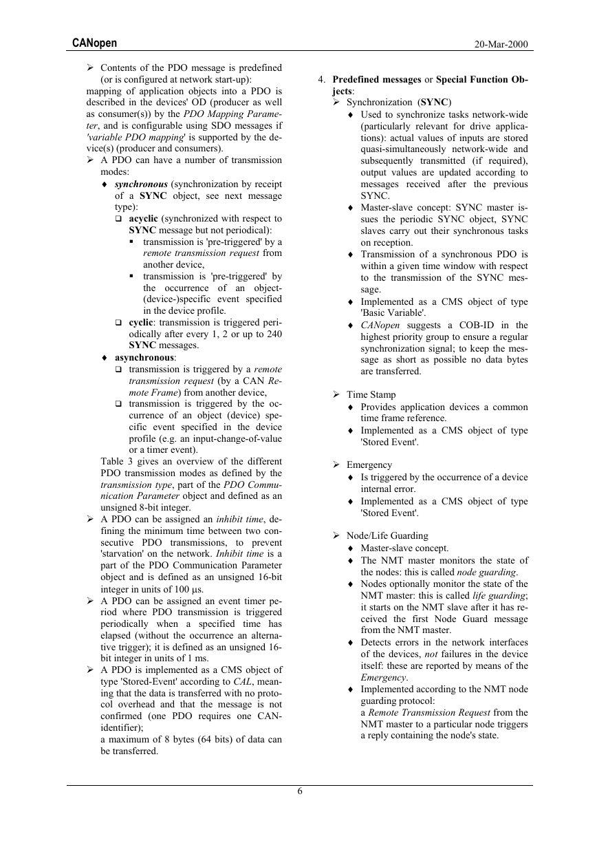
Table 3 gives an overview of the different
PDO transmission modes as defined by the
transmission type, part of the PDO Commu-
nication Parameter object and defined as an
unsigned 8-bit integer.
A PDO can be assigned an inhibit time, de-
fining the minimum time between two con-
secutive PDO
to prevent
'starvation' on the network. Inhibit time is a
part of the PDO Communication Parameter
object and is defined as an unsigned 16-bit
integer in units of 100 µs.
transmissions,
A PDO can be assigned an event timer pe-
riod where PDO transmission is triggered
periodically when a specified time has
elapsed (without the occurrence an alterna-
tive trigger); it is defined as an unsigned 16-
bit integer in units of 1 ms.
A PDO is implemented as a CMS object of
type 'Stored-Event' according to CAL, mean-
ing that the data is transferred with no proto-
col overhead and that the message is not
confirmed (one PDO requires one CAN-
identifier);
a maximum of 8 bytes (64 bits) of data can
be transferred.
6
20-Mar-2000
4. Predefined messages or Special Function Ob-
jects:
Synchronization (SYNC)
♦ Used to synchronize tasks network-wide
(particularly relevant for drive applica-
tions): actual values of inputs are stored
quasi-simultaneously network-wide and
subsequently transmitted (if required),
output values are updated according to
messages received after the previous
SYNC.
♦ Master-slave concept: SYNC master is-
sues the periodic SYNC object, SYNC
slaves carry out their synchronous tasks
on reception.
♦ Transmission of a synchronous PDO is
within a given time window with respect
to the transmission of the SYNC mes-
sage.
♦ Implemented as a CMS object of type
'Basic Variable'.
♦ CANopen suggests a COB-ID in the
highest priority group to ensure a regular
synchronization signal; to keep the mes-
sage as short as possible no data bytes
are transferred.
Time Stamp
♦ Provides application devices a common
time frame reference.
♦ Implemented as a CMS object of type
'Stored Event'.
Emergency
♦ Is triggered by the occurrence of a device
♦ Implemented as a CMS object of type
internal error.
'Stored Event'.
Node/Life Guarding
♦ Master-slave concept.
♦ The NMT master monitors the state of
the nodes: this is called node guarding.
♦ Nodes optionally monitor the state of the
NMT master: this is called life guarding;
it starts on the NMT slave after it has re-
ceived the first Node Guard message
from the NMT master.
♦ Detects errors in the network interfaces
of the devices, not failures in the device
itself: these are reported by means of the
Emergency.
♦ Implemented according to the NMT node
guarding protocol:
a Remote Transmission Request from the
NMT master to a particular node triggers
a reply containing the node's state.
�
CANopen
CAN
20-Mar-2000
I / O
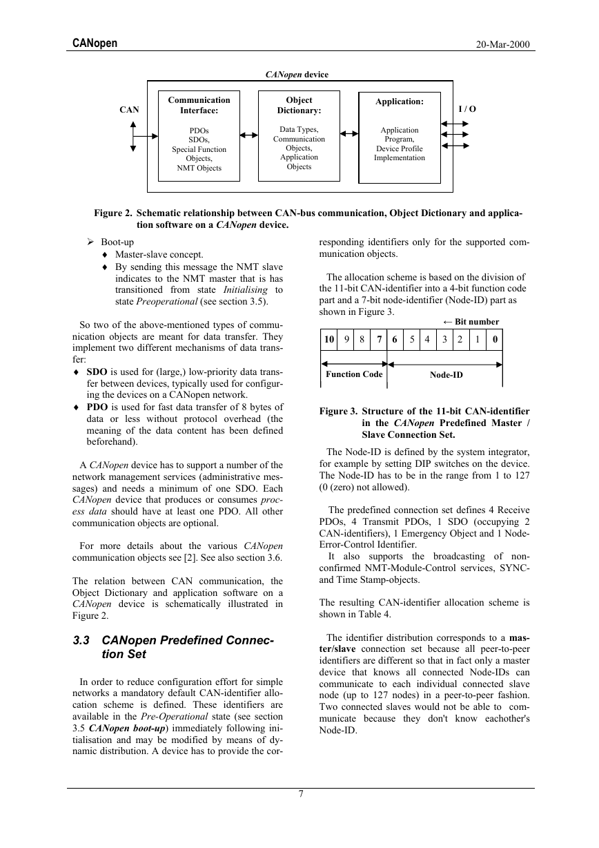
CANopen device
Object
Dictionary:
Data Types,
Communication
Objects,
Application
Objects
Application:
Application
Program,
Device Profile
Implementation
Communication
Interface:
PDOs
SDOs,
Special Function
Objects,
NMT Objects
Figure 2. Schematic relationship between CAN-bus communication, Object Dictionary and applica-
tion software on a CANopen device.
Boot-up
♦ Master-slave concept.
♦ By sending this message the NMT slave
indicates to the NMT master that is has
transitioned from state Initialising to
state Preoperational (see section 3.5).
So two of the above-mentioned types of commu-
nication objects are meant for data transfer. They
implement two different mechanisms of data trans-
fer:
♦ SDO is used for (large,) low-priority data trans-
fer between devices, typically used for configur-
ing the devices on a CANopen network.
♦ PDO is used for fast data transfer of 8 bytes of
data or less without protocol overhead (the
meaning of the data content has been defined
beforehand).
A CANopen device has to support a number of the
network management services (administrative mes-
sages) and needs a minimum of one SDO. Each
CANopen device that produces or consumes proc-
ess data should have at least one PDO. All other
communication objects are optional.
For more details about the various CANopen
communication objects see [2]. See also section 3.6.
The relation between CAN communication, the
Object Dictionary and application software on a
CANopen device is schematically illustrated in
Figure 2.
3.3 CANopen Predefined Connec-
tion Set
In order to reduce configuration effort for simple
networks a mandatory default CAN-identifier allo-
cation scheme is defined. These identifiers are
available in the Pre-Operational state (see section
3.5 CANopen boot-up) immediately following ini-
tialisation and may be modified by means of dy-
namic distribution. A device has to provide the cor-
7
responding identifiers only for the supported com-
munication objects.
The allocation scheme is based on the division of
the 11-bit CAN-identifier into a 4-bit function code
part and a 7-bit node-identifier (Node-ID) part as
shown in Figure 3.
← Bit number
10 9 8 7 6 5 4 3 2 1 0
Function Code
Node-ID
Figure 3. Structure of the 11-bit CAN-identifier
in the CANopen Predefined Master /
Slave Connection Set.
The Node-ID is defined by the system integrator,
for example by setting DIP switches on the device.
The Node-ID has to be in the range from 1 to 127
(0 (zero) not allowed).
The predefined connection set defines 4 Receive
PDOs, 4 Transmit PDOs, 1 SDO (occupying 2
CAN-identifiers), 1 Emergency Object and 1 Node-
Error-Control Identifier.
It also supports
the broadcasting of non-
confirmed NMT-Module-Control services, SYNC-
and Time Stamp-objects.
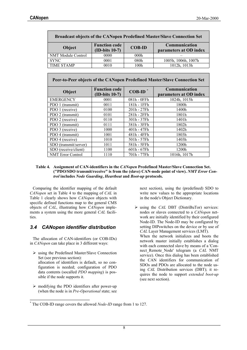
The resulting CAN-identifier allocation scheme is
shown in Table 4.
The identifier distribution corresponds to a mas-
ter/slave connection set because all peer-to-peer
identifiers are different so that in fact only a master
device that knows all connected Node-IDs can
communicate to each individual connected slave
node (up to 127 nodes) in a peer-to-peer fashion.
Two connected slaves would not be able to com-
municate because they don't know eachother's
Node-ID.
�
CANopen
20-Mar-2000
Broadcast objects of the CANopen Predefined Master/Slave Connection Set
Object
NMT Module Control
SYNC
TIME STAMP
Function code
(ID-bits 10-7)
0000
0001
0010
COB-ID
000h
080h
100h
Communication
parameters at OD index
1005h, 1006h, 1007h
1012h, 1013h
–
Peer-to-Peer objects of the CANopen Predefined Master/Slave Connection Set
Object
EMERGENCY
PDO 1 (transmit)
PDO 1 (receive)
PDO 2 (transmit)
PDO 2 (receive)
PDO 3 (transmit)
PDO 3 (receive)
PDO 4 (transmit)
PDO 4 (receive)
SDO (transmit/server)
SDO (receive/client)
NMT Error Control
Function code
(ID-bits 10-7)
0001
0011
0100
0101
0110
0111
1000
1001
1010
1011
1100
1110
COB-ID *
081h - 0FFh
181h - 1FFh
201h - 27Fh
281h - 2FFh
301h - 37Fh
381h - 3FFh
401h - 47Fh
481h - 4FFh
501h - 57Fh
581h - 5FFh
601h - 67Fh
701h - 77Fh
Communication
parameters at OD index
1024h, 1015h
1800h
1400h
1801h
1401h
1802h
1402h
1803h
1403h
1200h
1200h
1016h, 1017h
Table 4. Assignment of CAN-identifiers in the CANopen Predefined Master/Slave Connection Set.
("PDO/SDO transmit/receive" is from the (slave) CAN-node point of view). NMT Error Con-
trol includes Node Guarding, Heartbeat and Boot-up protocols.
Comparing the identifier mapping of the default
CANopen set in Table 4 to the mapping of CAL in
Table 1 clearly shows how CANopen objects with
specific defined functions map to the general CMS
objects of CAL, illustrating how CANopen imple-
ments a system using the more general CAL facili-
ties.
3.4 CANopen identifier distribution
The allocation of CAN-identifiers (or COB-IDs)
in CANopen can take place in 3 different ways:
using the Predefined Master/Slave Connection
Set (see previous section):
allocation of identifiers is default, so no con-
figuration is needed; configuration of PDO
data contents (socalled PDO mapping) is pos-
sible if the node supports it.
modifying the PDO identifiers after power-up
(when the node is in Pre-Operational state; see
next section), using the (predefined) SDO to
write new values to the appropriate locations
in the node's Object Dictionary.
using the CAL DBT (DistriBuTor) services:
nodes or slaves connected to a CANopen net-
work are initially identified by their configured
Node-ID. The Node-ID may be configured by
setting DIPswitches on the device or by use of
CAL Layer Management services (LMT).
When the network initializes and boots the
network master initially establishes a dialog
with each connected slave by means of a 'Con-
nect_Remote_Node' telegram (a CAL NMT
service). Once this dialog has been established
the CAN identifiers for communication of
SDOs and PDOs are allocated to the node us-
ing CAL Distribution services (DBT); it re-
quires the node to support extended boot-up
(see next section).
* The COB-ID range covers the allowed Node-ID range from 1 to 127.
8
�



 uCOS-III的任务调度算法研究.pdf
 STM32F103x8B_DS_CH_V10(7STM32中文数据手册).pdf
 FX2N系列PLC培训教程.pdf
 Modbus协议资料.pdf
 WM8978中文资料(芯片资料).doc
 5-1.【Codelab】HarmonyOS基于图像模块实现图库图片的四种常见操作.pdf
 GX Developer 编程软件使用说明.pdf
 MR-E伺服与FX3G接线图.pdf
 ATK-NEO-6M GPS模块常见问题汇总_201400721.pdf
 STM32F407ZGT6(芯片资料).pdf
 FM1715编程指南.pdf
 Profibus教程-7.PROFIBUS-FMS.pdf