/
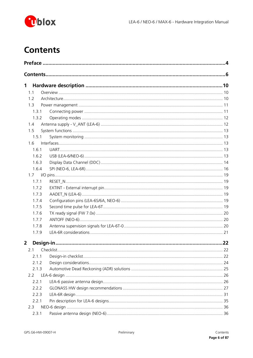
Preface
Contents
Hardware description
Overview
Architecture
Power management
Connecting power
VCC - main power
V_BCKP - backup battery
VDD_USB - USB interface power supply
Operating modes
Maximum Performance mode
Eco mode
Power Save mode
Antenna supply - V_ANT (LEA-6)
System functions
System monitoring
Interfaces
UART
USB (LEA-6/NEO-6)
USB external components
Display Data Channel (DDC)
Communicating to an I2C EEPROM with the GPS receiver as I2C master
SPI (NEO-6, LEA-6R)
Connecting SPI FLASH memory (NEO-6 modules)
SPI communication (connecting to an SPI master) NEO-6
Pin configuration with module as one of several slaves
I/O pins
RESET_N
EXTINT - External interrupt pin
AADET_N (LEA-6)
Configuration pins (LEA-6S/6A, NEO-6)
Second time pulse for LEA-6T
TX ready signal (FW 7.0x)
ANTOFF (NEO-6)
Antenna supervision signals for LEA-6T-0
LEA-6R considerations
Design-in
Checklist
Design-in checklist
Design considerations
Automotive Dead Reckoning (ADR) solutions
Software sensor interface
Hardware sensor interface
LEA-6 design
LEA-6 passive antenna design
GLONASS HW design recommendations
u-blox 6 GLONASS module
Wide RF path
Filter
Antenna
Active antenna
Passive Antenna
Module designs
Module design with active antenna
Module design with passive antenna
GLONASS SW integration
LEA-6R design
Connecting gyroscope and temperature sensor to the LEA-6R
Gyroscope requirements
Supported A/D converters
Supported temperature sensors
Forward / Backward indication
Odometer / Speedpulses
Pin description for LEA-6 designs
NEO-6 design
Passive antenna design (NEO-6)
Pin description for NEO-6 designs
MAX-6 design
MAX-6 passive antenna design
Pin description for MAX-6 designs
Layout
Footprint and paste mask
Placement
Antenna connection and grounding plane design
Antenna micro strip
Antenna and antenna supervisor
Passive antenna
Active antenna (LEA-6)
Active antenna bias power (LEA-6)
Short circuit protection
Active antenna supervisor (LEA-6)
Short and open circuit active antenna supervisor
Active antenna (NEO-6 and MAX-6)
External active antenna supervisor using ANTOFF (NEO-6)
External active antenna supervisor using ANTON (MAX-6)
External active antenna control (NEO-6)
External active antenna control (MAX-6)
GPS antenna placement for LEA-6R
Product handling
Packaging, shipping, storage and moisture preconditioning
Soldering
Soldering paste
Reflow soldering
Optical inspection
Cleaning
Repeated reflow soldering
Wave soldering
Hand soldering
Rework
Conformal coating
Casting
Grounding metal covers
Use of ultrasonic processes
EOS/ESD/EMI Precautions
Abbreviations
/Electrostatic discharge (ESD)
ESD handling precautions
ESD protection measures
Electrical Overstress (EOS)
EOS protection measures
Electromagnetic interference (EMI)
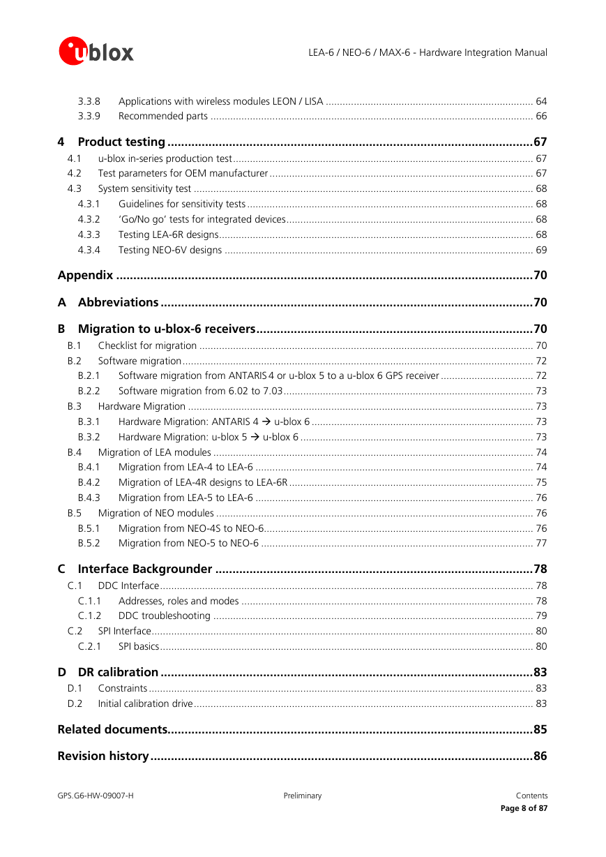
Applications with wireless modules LEON / LISA
Isolation between GPS and GSM antenna
Increasing jamming immunity
In-band jamming
Out-band jamming
GPS and GSM solution with integrated SMT antennas and chip SIM
Recommended parts
Recommended GPS & GLONASS active antenna (A1)
Product testing
u-blox in-series production test
Test parameters for OEM manufacturer
System sensitivity test
Guidelines for sensitivity tests
‘Go/No go’ tests for integrated devices
Testing LEA-6R designs
Direction signal
Speedpulse signal
Gyroscope (rate) input
Temperature sensor
Erase calibration
Testing NEO-6V designs
Appendix
Abbreviations
Migration to u-blox-6 receivers
Checklist for migration
Software migration
Software migration from ANTARIS 4 or u-blox 5 to a u-blox 6 GPS receiver
Software migration from 6.02 to 7.03
Hardware Migration
Hardware Migration: ANTARIS 4 ( u-blox 6
Hardware Migration: u-blox 5 ( u-blox 6
Migration of LEA modules
Migration from LEA-4 to LEA-6
Migration of LEA-4R designs to LEA-6R
Migration from LEA-5 to LEA-6
Migration of NEO modules
Migration from NEO-4S to NEO-6
Migration from NEO-5 to NEO-6
Interface Backgrounder
DDC Interface
Addresses, roles and modes
DDC troubleshooting
SPI Interface
SPI basics
DR calibration
Constraints
Initial calibration drive
Related documents
Revision history
Contact


