l
e
t
a
r
e
e
c
c
a
,
e
t
a
c
n
u
m
m
o
c
,
e
t
a
c
o
i
l
16.0 x 12.2 x 2.4 mm
NEO-6
u-blox 6 GPS Modules
Data Sheet
Abstract
Technical data sheet describing the cost effective, high-performance
u-blox 6 based NEO-6 series of GPS modules, that brings the high
performance of the u-blox 6 positioning engine to the miniature
NEO form factor.
These receivers combine a high level of integration capability with
flexible connectivity options in a small package. This makes them
perfectly suited for mass-market end products with strict size and
cost requirements.
www.u-blox.com
�
NEO-6 - Data Sheet
Document Information
Title
Subtitle
NEO-6
u-blox 6 GPS Modules
Document type
Data Sheet
Document number
GPS.G6-HW-09005-E
Document status
Document status information
Objective
Specification
This document contains target values. Revised and supplementary data will be published
later.
Advance
Information
Preliminary
This document contains data based on early testing. Revised and supplementary data will
be published later.
This document contains data from product verification. Revised and supplementary data
may be published later.
Released
This document contains the final product specification.
This document applies to the following products:
Name
NEO-6G
NEO-6Q
NEO-6M
NEO-6P
NEO-6V
NEO-6T
Type number
ROM/FLASH version
NEO-6G-0-001
NEO-6Q-0-001
NEO-6M-0-001
NEO-6P-0-000
NEO-6V-0-000
NEO-6T-0-000
ROM7.03
ROM7.03
ROM7.03
ROM6.02
ROM7.03
ROM7.03
PCN reference
UBX-TN-11047-1
UBX-TN-11047-1
UBX-TN-11047-1
N/A
N/A
N/A
This document and the use of any information contained therein, is subject to the acceptance of the u-blox terms and conditions. They
can be downloaded from www.u-blox.com.
u-blox makes no warranties based on the accuracy or completeness of the contents of this document and reserves the right to make
changes to specifications and product descriptions at any time without notice. Reproduction, use or disclosure to third parties without
express permission is strictly prohibited. Copyright © 2011, u-blox AG.
u-blox® is a registered trademark of u-blox Holding AG in the EU and other countries. ARM® is the registered trademark of ARM Limited in
the EU and other countries.
GPS.G6-HW-09005-E
Page 2 of 25
�
NEO-6 - Data Sheet
Contents
Contents .............................................................................................................................. 3
1.7.1
1.7.2
1.7.3
1.8
1.9
1.10
1.11
1.12
1 Functional description .................................................................................................. 5
1.1 Overview .............................................................................................................................................. 5
1.2
Product features ................................................................................................................................... 5
1.3 GPS performance .................................................................................................................................. 6
Block diagram ....................................................................................................................................... 7
1.4
Assisted GPS (A-GPS) ............................................................................................................................ 7
1.5
AssistNow Autonomous ....................................................................................................................... 7
1.6
1.7
Precision Timing .................................................................................................................................... 8
Time mode .................................................................................................................................... 8
Timepulse and frequency reference ............................................................................................... 8
Time mark ..................................................................................................................................... 8
Raw data .............................................................................................................................................. 8
Automotive Dead Reckoning ................................................................................................................ 8
Precise Point Positioning .................................................................................................................... 9
Oscillators ......................................................................................................................................... 9
Protocols and interfaces .................................................................................................................... 9
1.12.1 UART ............................................................................................................................................. 9
1.12.2 USB ............................................................................................................................................... 9
1.12.3 Serial Peripheral Interface (SPI) ....................................................................................................... 9
1.12.4 Display Data Channel (DDC) ........................................................................................................ 10
Antenna .......................................................................................................................................... 10
Power Management ....................................................................................................................... 10
1.14.1 Maximum Performance Mode ..................................................................................................... 10
1.14.2 Eco Mode .................................................................................................................................... 10
1.14.3 Power Save Mode ....................................................................................................................... 11
Configuration ................................................................................................................................. 11
1.15.1 Boot-time configuration .............................................................................................................. 11
Design-in ........................................................................................................................................ 11
1.13
1.14
1.15
1.16
2 Pin Definition .............................................................................................................. 12
Pin assignment ................................................................................................................................... 12
2.1
3 Electrical specifications .............................................................................................. 14
3.1
Absolute maximum ratings ................................................................................................................. 14
3.2 Operating conditions .......................................................................................................................... 15
Indicative power requirements ............................................................................................................ 15
3.3
SPI timing diagrams ............................................................................................................................ 16
3.4
Timing recommendations ............................................................................................................ 16
3.4.1
4 Mechanical specifications .......................................................................................... 17
GPS.G6-HW-09005-E
Page 3 of 25
�
5 Qualification and certification ................................................................................... 18
Reliability tests .................................................................................................................................... 18
Approvals ........................................................................................................................................... 18
5.1
5.2
NEO-6 - Data Sheet
6.1
6.1.1
6.1.1
6 Product handling & soldering .................................................................................... 19
Packaging ........................................................................................................................................... 19
Reels ........................................................................................................................................... 19
Tapes .......................................................................................................................................... 20
6.2 Moisture Sensitivity Levels ................................................................................................................... 21
6.3
Reflow soldering ................................................................................................................................. 21
ESD handling precautions ................................................................................................................... 21
6.4
7 Default settings .......................................................................................................... 22
8 Labeling and ordering information ........................................................................... 23
8.1
Product labeling .................................................................................................................................. 23
8.2
Explanation of codes........................................................................................................................... 23
8.3 Ordering information .......................................................................................................................... 24
Related documents........................................................................................................... 24
Revision history ................................................................................................................ 24
Contact .............................................................................................................................. 25
GPS.G6-HW-09005-E
Page 4 of 25
�
NEO-6 - Data Sheet
1 Functional description
1.1 Overview
The NEO-6 module series is a family of stand-alone GPS receivers featuring the high performance u-blox 6
positioning engine. These flexible and cost effective receivers offer numerous connectivity options in a miniature
16 x 12.2 x 2.4 mm package. Their compact architecture and power and memory options make NEO-6 modules
ideal for battery operated mobile devices with very strict cost and space constraints.
The 50-channel u-blox 6 positioning engine boasts a Time-To-First-Fix (TTFF) of under 1 second. The dedicated
acquisition engine, with 2 million correlators, is capable of massive parallel time/frequency space searches,
enabling it to find satellites instantly. Innovative design and technology suppresses jamming sources and
mitigates multipath effects, giving NEO-6 GPS receivers excellent navigation performance even in the most
challenging environments.
1.2 Product features
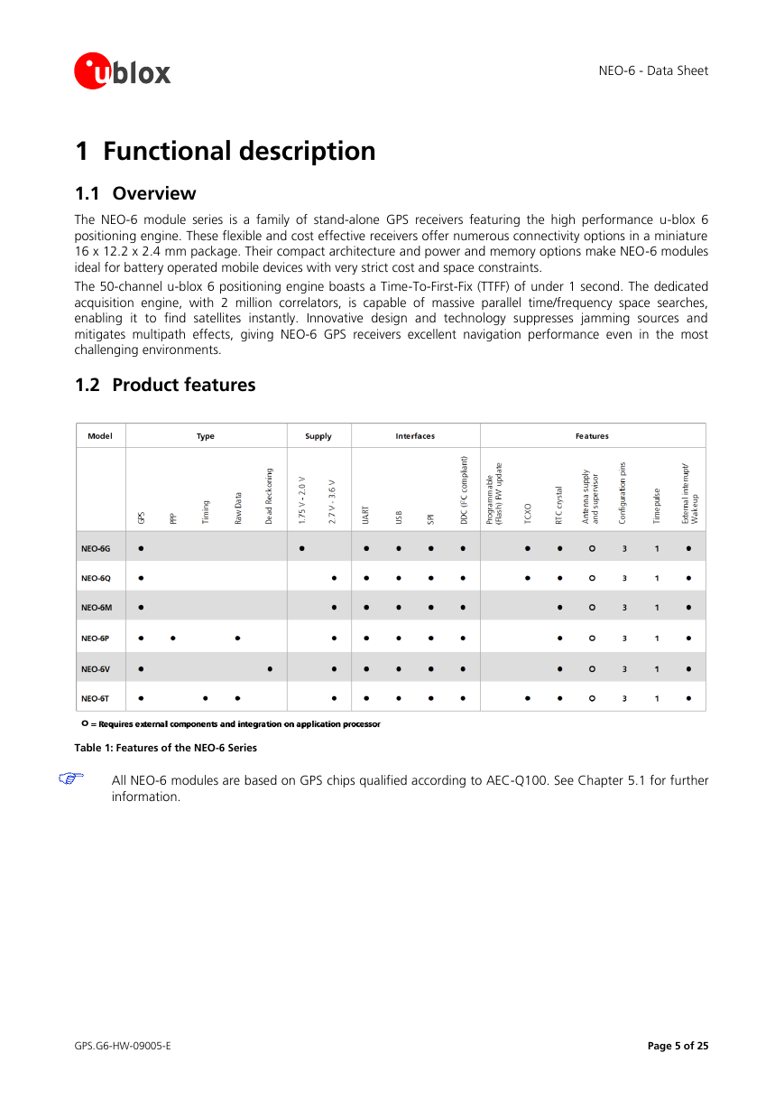
Table 1: Features of the NEO-6 Series
All NEO-6 modules are based on GPS chips qualified according to AEC-Q100. See Chapter 5.1 for further
information.
GPS.G6-HW-09005-E
Page 5 of 25
�
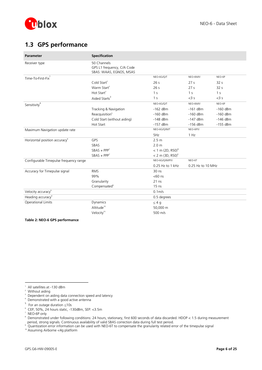
1.3 GPS performance
Parameter
Receiver type
1
Time-To-First-Fix
4
Sensitivity
Specification
50 Channels
GPS L1 frequency, C/A Code
SBAS: WAAS, EGNOS, MSAS
Cold Start2
Warm Start2
Hot Start2
3
Aided Starts
Tracking & Navigation
Reacquisition5
Cold Start (without aiding)
Maximum Navigation update rate
Horizontal position accuracy6
Configurable Timepulse frequency range
Accuracy for Timepulse signal
Velocity accuracy6
Heading accuracy6
Operational Limits
Table 2: NEO-6 GPS performance
Hot Start
GPS
SBAS
SBAS + PPP7
SBAS + PPP7
RMS
99%
Granularity
Compensated9
Dynamics
Altitude10
Velocity10
NEO-6 - Data Sheet
NEO-6G/Q/T
NEO-6M/V
NEO-6P
26 s
26 s
1 s
1 s
NEO-6G/Q/T
-162 dBm
-160 dBm
-148 dBm
-157 dBm
NEO-6G/Q/M/T
5Hz
2.5 m
27 s
27 s
1 s
<3 s
NEO-6M/V
-161 dBm
-160 dBm
-147 dBm
-156 dBm
NEO-6P/V
1 Hz
32 s
32 s
1 s
<3 s
NEO-6P
-160 dBm
-160 dBm
-146 dBm
-155 dBm
2.0 m
< 1 m (2D, R50)8)
< 2 m (3D, R50)8
NEO-6G/Q/M/P/V
NEO-6T
0.25 Hz to 1 kHz
0.25 Hz to 10 MHz
30 ns
<60 ns
21 ns
15 ns
0.1m/s
0.5 degrees
4 g
50,000 m
500 m/s
1 All satellites at -130 dBm
2 Without aiding
3 Dependent on aiding data connection speed and latency
4 Demonstrated with a good active antenna
5 For an outage duration 10s
6 CEP, 50%, 24 hours static, -130dBm, SEP: <3.5m
7 NEO-6P only
8 Demonstrated under following conditions: 24 hours, stationary, first 600 seconds of data discarded. HDOP < 1.5 during measurement
period, strong signals. Continuous availability of valid SBAS correction data during full test period.
9 Quantization error information can be used with NEO-6T to compensate the granularity related error of the timepulse signal
10 Assuming Airborne <4g platform
GPS.G6-HW-09005-E
Page 6 of 25
�
1.4 Block diagram
NEO-6 - Data Sheet
Figure 1: Block diagram (For available options refer to the product features table in section 1.2).
1.5 Assisted GPS (A-GPS)
Supply of aiding information like ephemeris, almanac, rough last position and time and satellite status and an
optional time synchronization signal will reduce time to first fix significantly and improve the acquisition
sensitivity. All NEO-6 modules support the u-blox AssistNow Online and AssistNow Offline A-GPS services11 and
are OMA SUPL compliant.
1.6 AssistNow Autonomous
AssistNow Autonomous provides functionality similar to Assisted-GPS without the need for a host or external
network connection. Based on previously broadcast satellite ephemeris data downloaded to and stored by the
GPS receiver, AssistNow Autonomous automatically generates accurate satellite orbital data (“AssistNow
Autonomous data”) that is usable for future GPS position fixes. AssistNow Autonomous data is reliable for up to
3 days after initial capture.
u-blox’ AssistNow Autonomous benefits are:
Faster position fix
No connectivity required
Complementary with AssistNow Online and Offline services
No integration effort, calculations are done in the background
For more details see the u-blox 6 Receiver Description including Protocol Specification [2].
11 AssistNow Offline requires external memory.
GPS.G6-HW-09005-E
Page 7 of 25
�
NEO-6 - Data Sheet
1.7 Precision Timing
1.7.1 Time mode
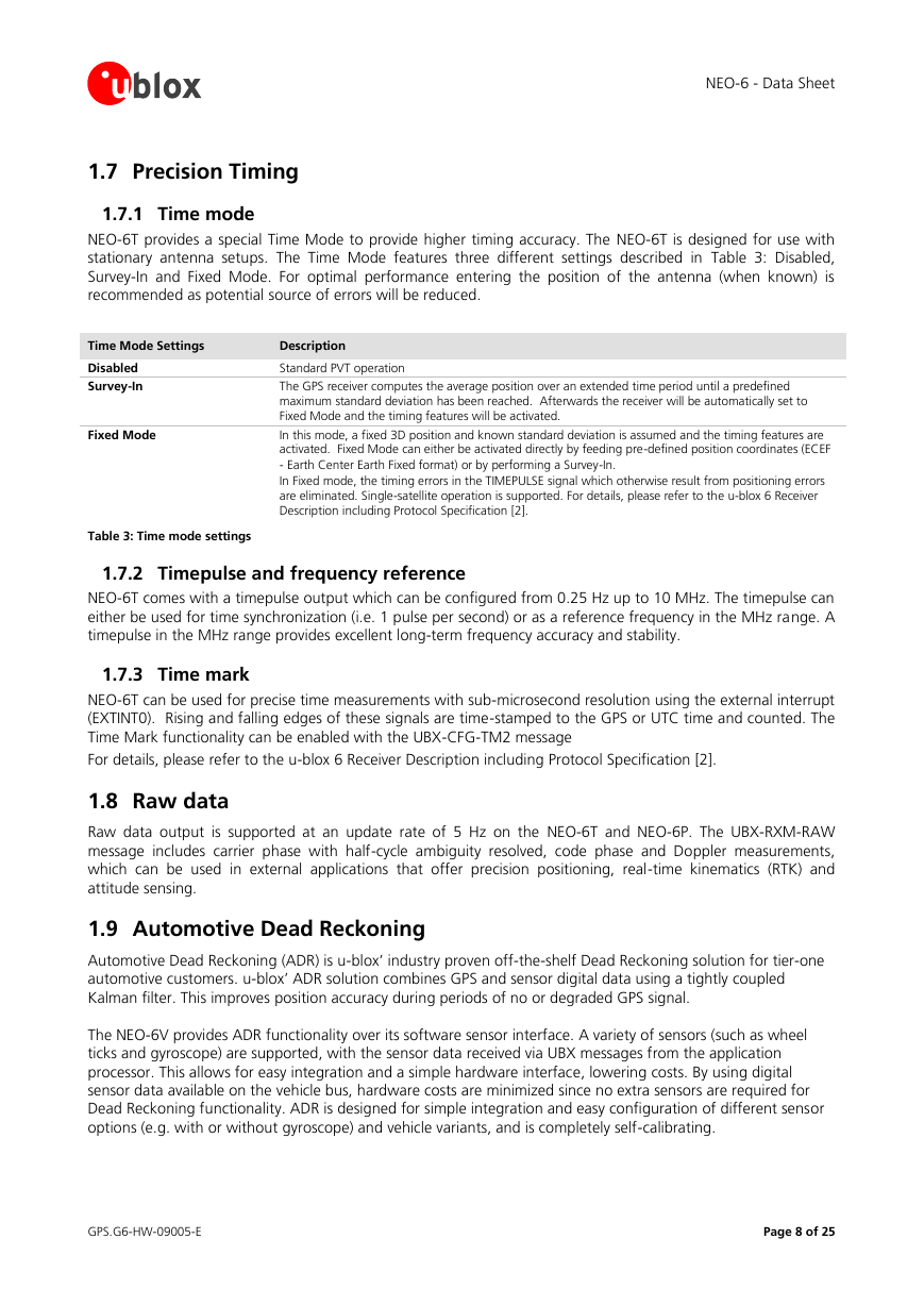
NEO-6T provides a special Time Mode to provide higher timing accuracy. The NEO-6T is designed for use with
stationary antenna setups. The Time Mode features three different settings described in Table 3: Disabled,
Survey-In and Fixed Mode. For optimal performance entering the position of the antenna (when known) is
recommended as potential source of errors will be reduced.
Time Mode Settings
Description
Disabled
Survey-In
Fixed Mode
Standard PVT operation
The GPS receiver computes the average position over an extended time period until a predefined
maximum standard deviation has been reached. Afterwards the receiver will be automatically set to
Fixed Mode and the timing features will be activated.
In this mode, a fixed 3D position and known standard deviation is assumed and the timing features are
activated. Fixed Mode can either be activated directly by feeding pre-defined position coordinates (ECEF
- Earth Center Earth Fixed format) or by performing a Survey-In.
In Fixed mode, the timing errors in the TIMEPULSE signal which otherwise result from positioning errors
are eliminated. Single-satellite operation is supported. For details, please refer to the u-blox 6 Receiver
Description including Protocol Specification [2].
Table 3: Time mode settings
1.7.2 Timepulse and frequency reference
NEO-6T comes with a timepulse output which can be configured from 0.25 Hz up to 10 MHz. The timepulse can
either be used for time synchronization (i.e. 1 pulse per second) or as a reference frequency in the MHz range. A
timepulse in the MHz range provides excellent long-term frequency accuracy and stability.
1.7.3 Time mark
NEO-6T can be used for precise time measurements with sub-microsecond resolution using the external interrupt
(EXTINT0). Rising and falling edges of these signals are time-stamped to the GPS or UTC time and counted. The
Time Mark functionality can be enabled with the UBX-CFG-TM2 message
For details, please refer to the u-blox 6 Receiver Description including Protocol Specification [2].
1.8 Raw data
Raw data output is supported at an update rate of 5 Hz on the NEO-6T and NEO-6P. The UBX-RXM-RAW
message includes carrier phase with half-cycle ambiguity resolved, code phase and Doppler measurements,
which can be used in external applications that offer precision positioning, real-time kinematics (RTK) and
attitude sensing.
1.9 Automotive Dead Reckoning
Automotive Dead Reckoning (ADR) is u-blox’ industry proven off-the-shelf Dead Reckoning solution for tier-one
automotive customers. u-blox’ ADR solution combines GPS and sensor digital data using a tightly coupled
Kalman filter. This improves position accuracy during periods of no or degraded GPS signal.
The NEO-6V provides ADR functionality over its software sensor interface. A variety of sensors (such as wheel
ticks and gyroscope) are supported, with the sensor data received via UBX messages from the application
processor. This allows for easy integration and a simple hardware interface, lowering costs. By using digital
sensor data available on the vehicle bus, hardware costs are minimized since no extra sensors are required for
Dead Reckoning functionality. ADR is designed for simple integration and easy configuration of different sensor
options (e.g. with or without gyroscope) and vehicle variants, and is completely self-calibrating.
GPS.G6-HW-09005-E
Page 8 of 25
�

