CANopen
A
i
u CANopen Conformance TestC
u Modeling
u Physical Layer
u Communication Objects
u Network Management
u Identifier Distribution
u Framework for Programmable Devices
u Electronic Data Sheet (EDS)
u Device Profiles
CiA
CANopen is a networking system based on the CAN serial bus.
CANopen assumes that the devices hardware has a CAN transceiver
and CAN controller as specified in ISO 11898.
CANopen profile family specifies standardized communication
mechanisms and device functionality. The profile family is available
and maintained by CAN in Automation (CiA), the international users
and manufacturers group and may be implemented license-free.
The CANopen specifications cover application layer and
communication profile (CiA DS-301) as well as a framework for
programmable devices (CiA DSP-302), recommendations for cables
and connectors (CiA DRP-303-1) and SI units and prefix
representations (CiA DRP-303-2). Additional application-specific
frameworks may apply in parallel. CANopen is supplemented by a
number of standardized device profiles, interface profiles as well as
application profiles (CiA DS-4XX).
CANopen was originally designed for motion-oriented industrial
control systems, such as handling systems. But CANopen networks
are also used in other application fields, e.g. public transportation, off-
road vehicles, medical equipment, maritime electronics, and building
automation.
© CiA u Am Weichselgarten 26 u D-91058 Erlangen u headquarters@can-cia.de
�
CANopen Reference Model
CANopen Reference Model
Device
Device
Profile
Profile
Interface
Interface
Profile
Profile
Application
Application
Profile
Profile
Manager
Manager
Profile
Profile
manu-
manu-
facturer-
facturer-
specific
specific
Profile
Profile
Frameworks (e.g. for Programmable Devices)
Frameworks (e.g. for Programmable Devices)
Communication Profile(s)
Communication Profile(s)
Application Layer
Application Layer
Data Link Layer and High-Speed Transceiver (ISO 11898)
Data Link Layer and High-Speed Transceiver (ISO 11898)
Bit-Timing and Connector Pin-Assignment
Bit-Timing and Connector Pin-Assignment
bus lines
CiA
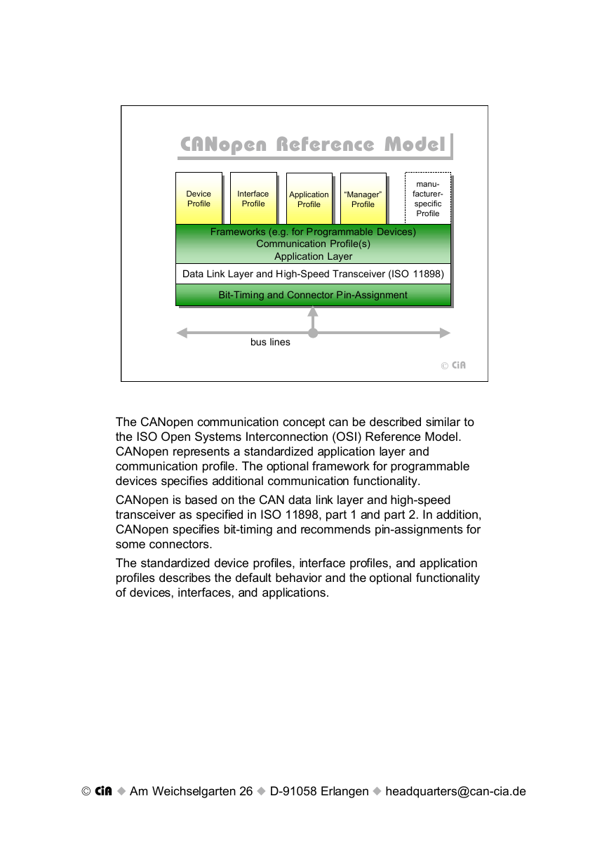
The CANopen communication concept can be described similar to
the ISO Open Systems Interconnection (OSI) Reference Model.
CANopen represents a standardized application layer and
communication profile. The optional framework for programmable
devices specifies additional communication functionality.
CANopen is based on the CAN data link layer and high-speed
transceiver as specified in ISO 11898, part 1 and part 2. In addition,
CANopen specifies bit-timing and recommends pin-assignments for
some connectors.
The standardized device profiles, interface profiles, and application
profiles describes the default behavior and the optional functionality
of devices, interfaces, and applications.
© CiA u Am Weichselgarten 26 u D-91058 Erlangen u headquarters@can-cia.de
�
Protocol Layer Interactions
Protocol Layer Interactions
Transmitting
Device
CANopen
Application
Layer
CAN Data Link
Layer
CAN Physical
Layer
Object at Index
ID + Data
...
ID + data
CAN_L CAN_L
CAN_H
Receiving
Device
CANopen
Application
Layer
CAN Data Link
Layer
CAN Physical
Layer
CiA
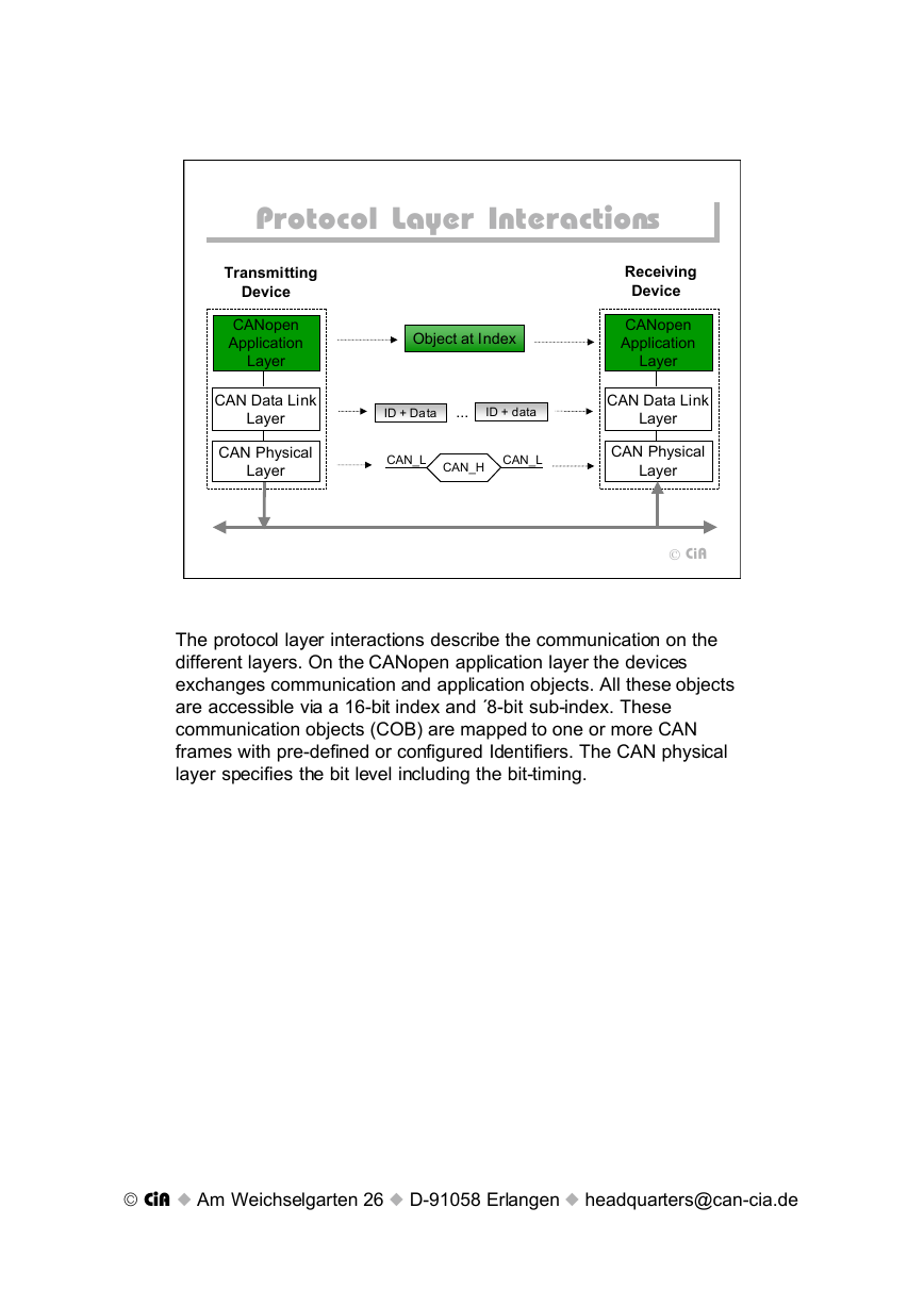
The protocol layer interactions describe the communication on the
different layers. On the CANopen application layer the devices
exchanges communication and application objects. All these objects
are accessible via a 16-bit index and «8-bit sub-index. These
communication objects (COB) are mapped to one or more CAN
frames with pre-defined or configured Identifiers. The CAN physical
layer specifies the bit level including the bit-timing.
© CiA u Am Weichselgarten 26 u D-91058 Erlangen u headquarters@can-cia.de
�
Bit-Timing Specification
Bit-Timing Specification
Time Quantum (TQ)
Sample Point
1 Mbit/s
TQ=125ns
800 kbit/s
TQ=125ns
10-500 kbit/s
TQ=250ns..
6,25ms
1 2 3 4 5 6 7 8
Nominal Bit Time
1 2 3 4 5 6 7 8 9 10
1 2 3 4 5 6 7 8 9 10 11 12 13 14 15 16
CiA
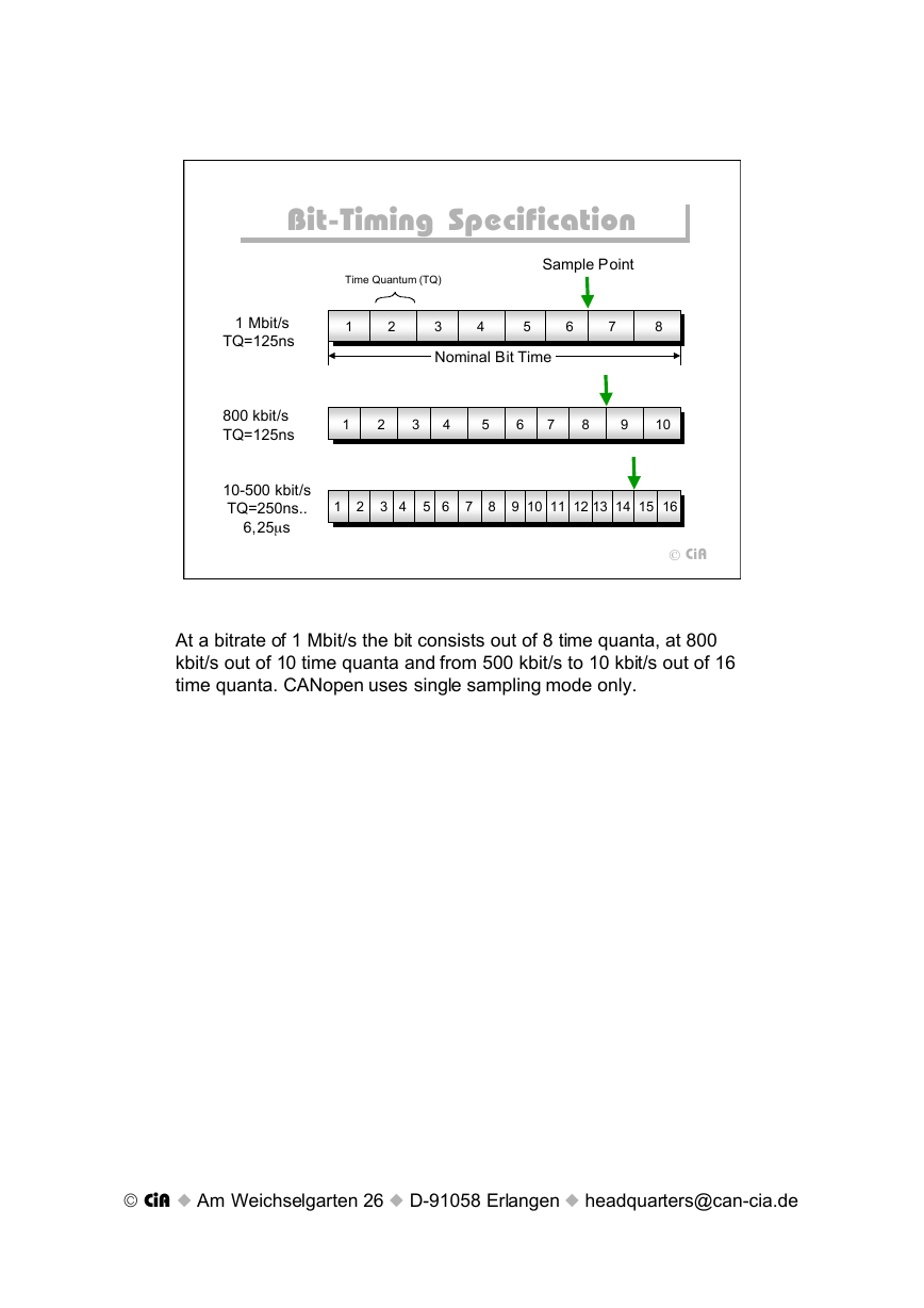
At a bitrate of 1 Mbit/s the bit consists out of 8 time quanta, at 800
kbit/s out of 10 time quanta and from 500 kbit/s to 10 kbit/s out of 16
time quanta. CANopen uses single sampling mode only.
© CiA u Am Weichselgarten 26 u D-91058 Erlangen u headquarters@can-cia.de
�
Bit-Timing (2)
Bit-Timing (2)
Length of
Location of
Index
Bit rate
Nominal
bit time
Number of
time quanta
time
Bus length (1)
1 Mbit/s
25 m
tb
1 ms
800 kbit/s
1.25 ms
50 m
500 kbit/s
2 ms
100 m
250 kbit/s
250 m (2)
125 kbit/s
500 m (2)
50 kbit/s
1000 m (3)
20 kbit/s
2500 m (3)
10 kbit/s
5000 m (3)
4 ms
8 ms
20 ms
50 ms
100 ms
per bit
quantum tq
8
10
16
16
16
16
16
16
125 ns
125 ns
125 ns
250 ns
500 ns
1.25 ms
3.125 ms
6.25 ms
sample
point
6 tq
(750 ns)
8 tq
(1 ms)
14 tq
(1.75 ms)
14 tq
(3.5 ms)
14 tq
(7 ms)
14 tq
(17.5 ms)
14 tq
(43.75 ms)
14 tq
(87.5 ms)
0
1
2
3
4
5
6
7
CiA
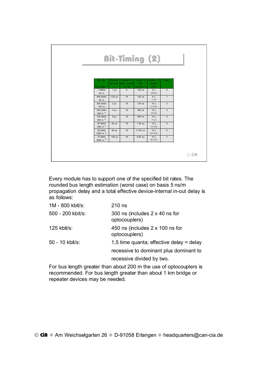
Every module has to support one of the specified bit rates. The
rounded bus length estimation (worst case) on basis 5 ns/m
propagation delay and a total effective device-internal in-out delay is
as follows:
1M - 800 kbit/s:
500 - 200 kbit/s:
210 ns
300 ns (includes 2 x 40 ns for
optocouplers)
450 ns (includes 2 x 100 ns for
optocouplers)
1,5 time quanta; effective delay = delay
recessive to dominant plus dominant to
recessive divided by two.
125 kbit/s:
50 - 10 kbit/s:
For bus length greater than about 200 m the use of optocouplers is
recommended. For bus length greater than about 1 km bridge or
repeater devices may be needed.
© CiA u Am Weichselgarten 26 u D-91058 Erlangen u headquarters@can-cia.de
�
Pin Assignment
Pin Assignment
9-pin D-Sub: DIN 41652
-
-
Reserved
CAN_L bus line dominant low
CAN Ground
Reserved
Pin Signal Description
1
2 CAN_L
3 CAN_GND
4
5 (CAN_SHLD) Optional CAN Shield
6 GND
7 CAN_H
8 -
9 (CAN_V+)
Optional Ground
CAN_H bus line dominant high
Reserved
Optional CAN external positive supply
CiA
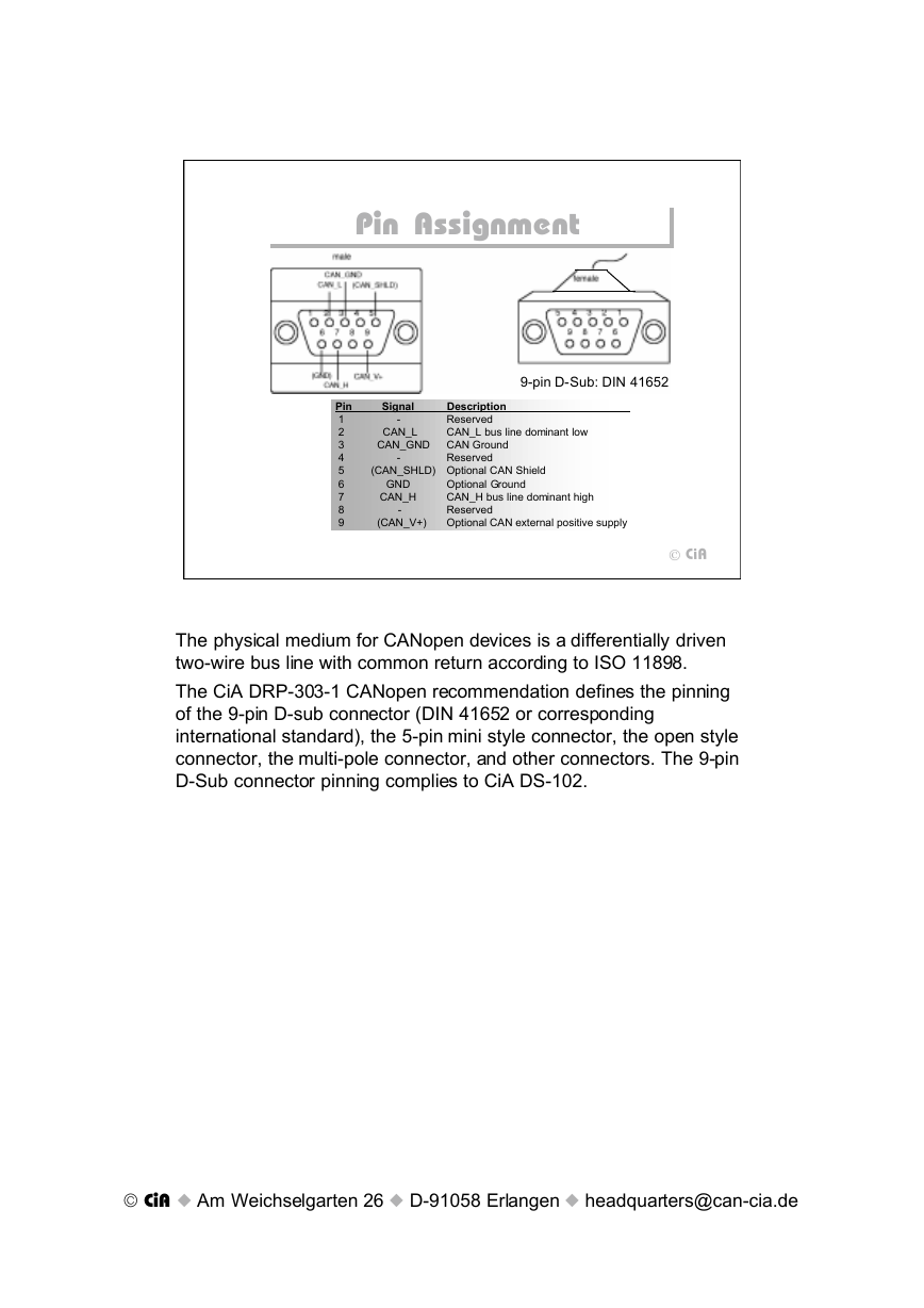
The physical medium for CANopen devices is a differentially driven
two-wire bus line with common return according to ISO 11898.
The CiA DRP-303-1 CANopen recommendation defines the pinning
of the 9-pin D-sub connector (DIN 41652 or corresponding
international standard), the 5-pin mini style connector, the open style
connector, the multi-pole connector, and other connectors. The 9-pin
D-Sub connector pinning complies to CiA DS-102.
© CiA u Am Weichselgarten 26 u D-91058 Erlangen u headquarters@can-cia.de
�
Mini Style Connector
Mini Style Connector
5-pin Mini Style Connector
: ANSI/B93.55M-1981
male
3
female
3
4
5
2
2
1
1
4
5
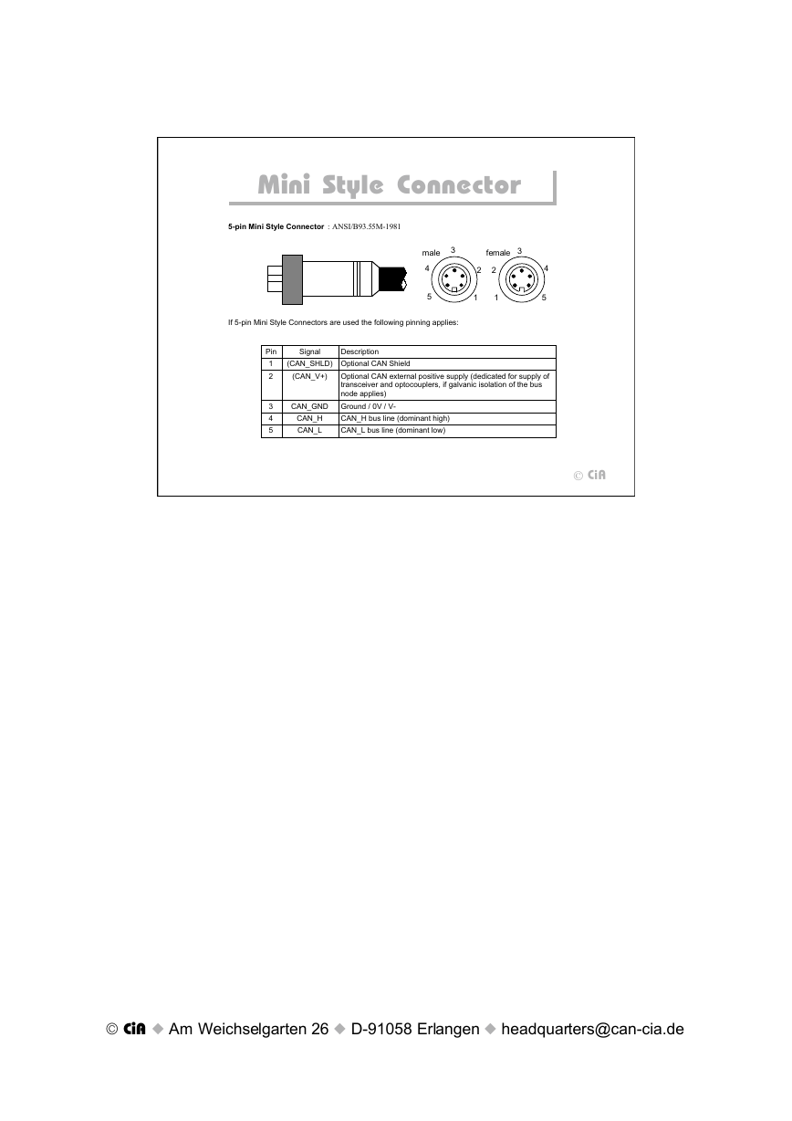
If 5-pin Mini Style Connectors are used the following pinning applies:
Pin
1
2
3
4
5
Signal
Description
(CAN_SHLD) Optional CAN Shield
(CAN_V+)
CAN_GND
CAN_H
CAN_L
Optional CAN external positive supply (dedicated for supply of
transceiver and optocouplers, if galvanic isolation of the bus
node applies)
Ground / 0V / V-
CAN_H bus line (dominant high)
CAN_L bus line (dominant low)
CiA
© CiA u Am Weichselgarten 26 u D-91058 Erlangen u headquarters@can-cia.de
�
Open Style Connector
Open Style Connector
Open Style Connector
female
male
3
1
2
4
5
1 2 3 4 5
If Open Style Connectors are used the following pinning is recommended:
Pin
1
2
3
4
5
Signal
CAN_GND
CAN_L
Description
Ground / 0 V / V-
CAN_L bus line (dominant low)
(CAN_SHLD) Optional CAN Shield
CAN_H
(CAN_V+)
CAN_H bus line (dominant high)
Optional CAN external positive supply (dedicated for supply of
transceiver and optocouplers, if galvanic isolation of the bus
node applies)
CiA
© CiA u Am Weichselgarten 26 u D-91058 Erlangen u headquarters@can-cia.de
�
