CiA TR 308
CANopen
Performance measurement basics
Version: 1.0.1
24 Jan 2006
CAN in Automation (CiA) e. V.
�
Performance measurement basics –
Changes
Publication of Version 1.0
Renaming
HISTORY
Date
01.12.2001
24.01.2006
General information on licensing and patents
CAN in AUTOMATION (CiA) calls attention to the possibility that some of the elements of this
CiA specification may be subject of patent rights. CiA shall not be responsible for identifying
any or all such patent rights.
Because this specification is licensed free of charge, there is no warranty for this
specification, to the extent permitted by applicable law. Except when otherwise stated in
writing the copyright holder and/or other parties provide this specification “as is” without
warranty of any kind, either expressed or implied, including, but not limited to, the implied
warranties of merchantability and fitness for a particular purpose. The entire risk as to the
correctness and completeness of the specification is with you. Should this specification prove
failures, you assume the cost of all necessary servicing, repair or correction.
© CiA 2008
All rights reserved. Unless otherwise specified, no part of this publication may be reproduced or
utilized in any form or by any means, electronic or mechanical, including photocopying and microfilm,
without permission in writing from CiA at the address below.
CAN in Automation e. V.
Kontumazgarten 3
DE - 90429 Nuremberg, Germany
Tel.: +49-911-928819-0
Fax: +49-911-928819-79
Url: www.can-cia.org
Email: headquarters@can-cia.org
2
CiA 2008 – All rights reserved
�
Performance measurement basics
CONTENTS
1 Scope ............................................................................................................................... 4
2 References ....................................................................................................................... 4
3 Abbreviations .................................................................................................................... 4
4 Pre-definitions................................................................................................................... 5
5 System characteristics ...................................................................................................... 6
5.1 General ................................................................................................................... 6
5.2 Measuring reaction times......................................................................................... 6
5.2.1 General ....................................................................................................... 6
5.2.2 PDO turnaround time ................................................................................... 6
5.2.3 SYNC Reaction Time ................................................................................... 7
5.2.4 SDO response time ..................................................................................... 7
5.3 Boot-up time ............................................................................................................ 8
5.3.1 Guard response time and guard cycle time .................................................. 8
5.4 Cycle time measurement ......................................................................................... 8
5.4.1 General ....................................................................................................... 8
5.4.2 PDO timer event cycle time ......................................................................... 8
5.4.3 Communication cycle period ........................................................................ 9
5.4.4 Guard cycle time.......................................................................................... 9
5.4.5 Heartbeat cycle time .................................................................................... 9
6 Busload Generator............................................................................................................ 9
6.1 General ................................................................................................................... 9
6.2 Table Structure...................................................................................................... 10
6.3 Scenarios .............................................................................................................. 10
6.4 Busload Generator Tables ..................................................................................... 11
6.4.1 1 Mbit/sec.................................................................................................. 11
6.4.2 800 kbit/sec ............................................................................................... 13
6.4.3 500 kbit/sec ............................................................................................... 15
6.4.4 250 kbit/sec ............................................................................................... 17
6.4.5 125 kbit/sec ............................................................................................... 19
6.4.6 50 kbit/sec ................................................................................................. 22
6.4.7 20 kbit/sec ................................................................................................. 24
6.4.8 10 kbit/sec ................................................................................................. 26
CiA 2008 – All rights reserved
3
�
Performance measurement basics –
1 Scope
CANopen is a field-bus protocol used in many diverse application: CANopen networks can be
found not only in various industrial applications ranging from printing machines and robots to
process controls, but also in ships, building automation, trains, trucks and even in coffee
machines. CANopen is used for high accuracy drive synchronisation and for flight data
recording. It is also in use in medical applications and has been chosen as the standard
communication protocol for passenger information systems in public transport.
This variety of applications leads to totally different requirements in regard to CANopen
performance. The critical real-time requirement of one application may be a short response
time to synchronisation messages relating to a single process data object, where as a
different application may expect a node with many event driven process data objects to send
these objects immediately after a certain input signal has changed. With drive synchronisation
for instance, some applications need long time accuracy of the sync cycle and tolerate almost
any jitter of a single sync message, and others require minimal jitter and tolerate long term
drift.
Regarding most other bus systems it is fairly straightforward to measure and publish
communication performance figures for most node types. With CANopen this is not the case:
the capability of CANopen to tailor the communication to the application needs makes it very
difficult to determine valuable performance figures that are independent of the specific
network set-up. For example, figures relating to reaction times not only depend on the
processor used, but on the actual bus load, on the type of CAN controller being used, on the
actual number and types of I/Os or drives connected, on the number and transmission types
of the process data objects, on the guard or heartbeat cycle, and on many other settings and
parameters in the object dictionary. Developing a CANopen node always involves a certain
trade-off between performance and
is a multi-
dimensional value.
functionality. Therefore performance
The goal of this performance specification is to name and define a set of CANopen
communication performance
to compare devices and
implementations within a specific application environment. It is not the aim of this paper to
define a standard performance-measuring environment, as this would lead to implementations
that perform fine in exactly this environment but disappoint under most other conditions.
that may be used
figures
However, in order to establish some comparable conditions, this specification defines a
number of standard busloads that may be used to simulate or enhance application
environments.
This performance test specification is aimed both at CANopen device developers and at
CANopen system integrators. It may help developers determine relative performance figures
regarding two implementation variants, thus leading to better devices and it may help system
integrators to ask the right questions, thus leading to better CANopen networks.
2 References
/CiA301/
/ISO118981/
CiA DS 301, CANopen - Communication Profile for Industrial Systems, v 4.01,
June 2000
ISO 11898, Road vehicles - Interchange of digital information - Controller area
network (CAN) for high-speed communication, 1993
3 Abbreviations
3.1 CAN
Controller Area Network is an internationally standardized serial bus system.
4
CiA 2008 – All rights reserved
�
Performance measurement basics
3.2 COB
Communication Object. A unit of transportation in a CAN network. Data must be sent across a
CAN Network inside a COB. A COB can contain at most 8 bytes of data.
3.3 COB ID
Each COB is uniquely identified in a CAN network by a number called the COB Identifier
(COB ID). The COB ID determines the priority of that COB for the MAC sub layer.
3.4 Remote COB
A COB whose transmission can be requested by another device.
3.5 CSDO
Client SDO.
3.6 DLC
Data Length Code of a CAN message.
3.7 DUT
Device under test
3.8 NMT
Network Management. One of the service elements of the application layer in the CAN
Reference Model. The NMT serves to configure, initialise and handle errors in a CAN network.
3.9 PDO
Process Data Object.
3.10 RPDO
Receive PDO.
3.11 SDO
Service Data Object.
3.12 SSDO
Server SDO.
3.13 SYNC
Synchronisation Object.
3.14 TPDO
Transmit PDO.
4 Pre-definitions
In this document, the end marker of a CAN telegram is used as the reference point for all
measurements regarding the time difference between two telegrams. This allows for the
measurement of message times via the CAN-Receive/Transmit interrupt.
CiA 2008 – All rights reserved
5
�
Performance measurement basics –
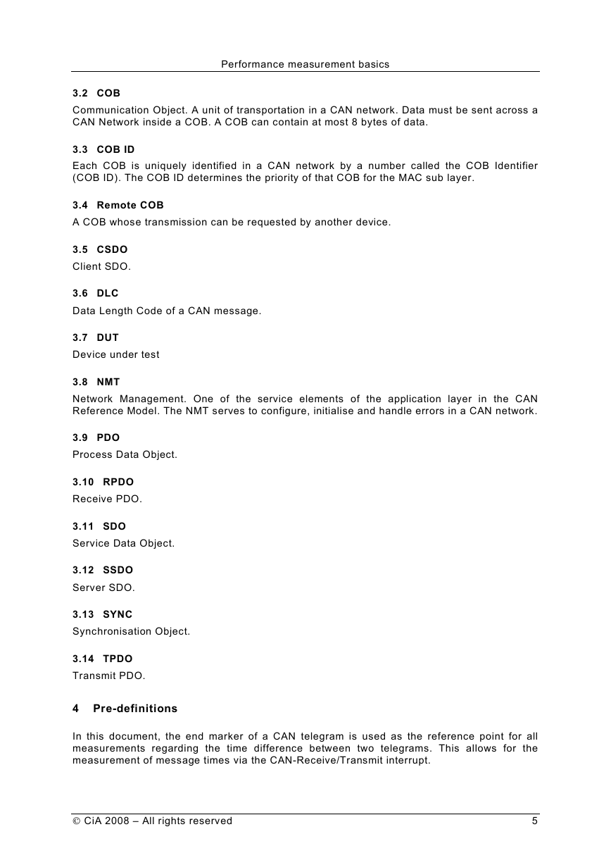
Figure 1 – Definition of the time stamp
In the case that transmission start times are defined (see 6), this can only be done using
internal timers, since it is not possible to precisely know when a message actually appears on
the bus. Desired transmission start times can therefore only be defined as the time difference
between two desired values. If a precise value is required for a transmission start time, this
must be measured using the transmit interrupt following successful transmission.
5 System characteristics
5.1 General
To attain results, which are comparable, it is necessary to define all relevant system
characteristics and in doing so to give a unique definition of terms used. This document
describes system characteristics, which are not necessarily relevant for all device types,
however in the case that they are relevant for a device, then the corresponding term must be
used. Correspondingly it may be necessary to define additional characteristics, which are
device specific. The individual CANopen device profiles must cater for such device specific
characteristics.
It is possible to classify system characteristics into two categories: reaction times and cyclic
times.
5.2 Measuring reaction times
5.2.1
General
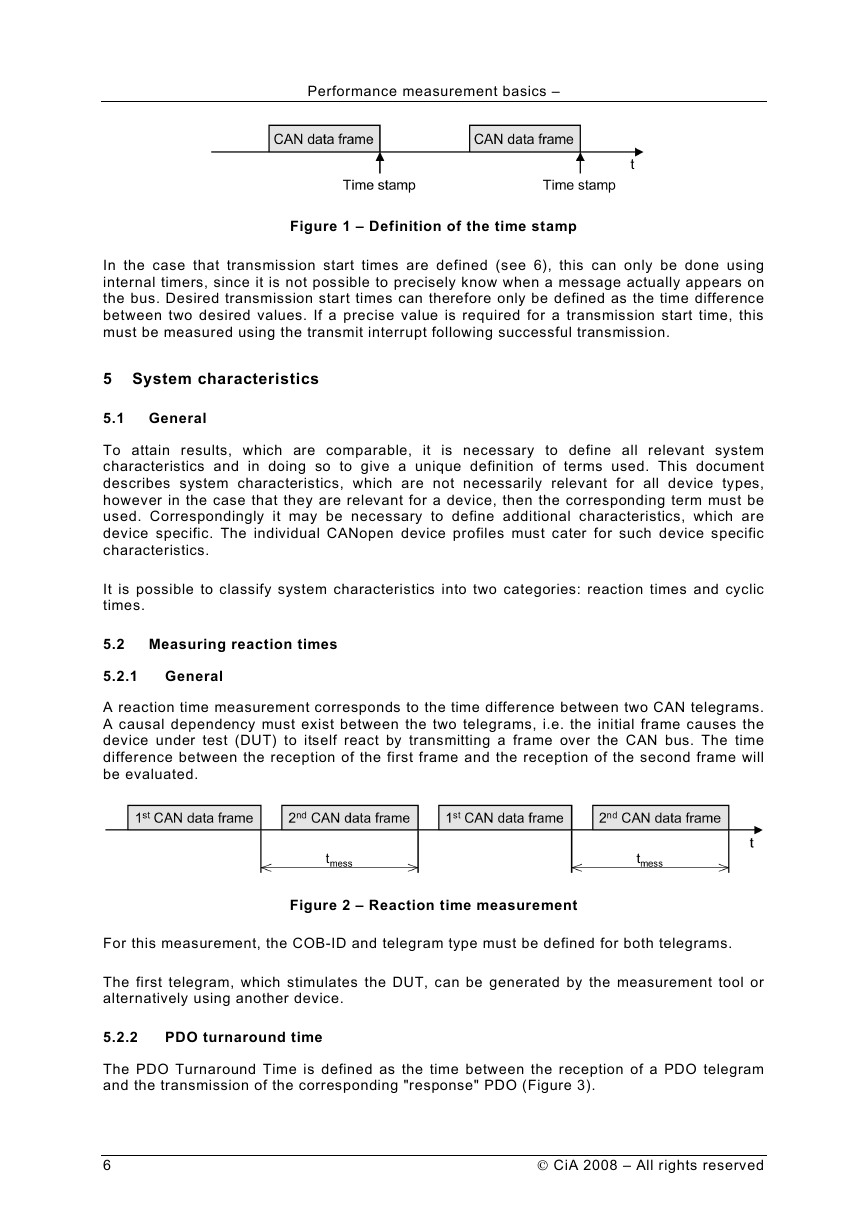
A reaction time measurement corresponds to the time difference between two CAN telegrams.
A causal dependency must exist between the two telegrams, i.e. the initial frame causes the
device under test (DUT) to itself react by transmitting a frame over the CAN bus. The time
difference between the reception of the first frame and the reception of the second frame will
be evaluated.
Figure 2 – Reaction time measurement
For this measurement, the COB-ID and telegram type must be defined for both telegrams.
The first telegram, which stimulates the DUT, can be generated by the measurement tool or
alternatively using another device.
5.2.2
PDO turnaround time
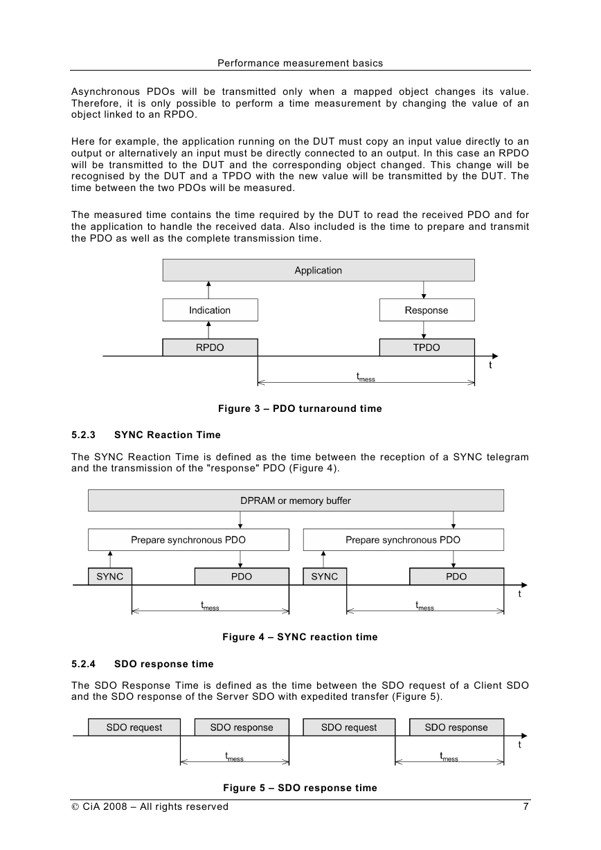
The PDO Turnaround Time is defined as the time between the reception of a PDO telegram
and the transmission of the corresponding "response" PDO (Figure 3).
6
CiA 2008 – All rights reserved
�
Performance measurement basics
Asynchronous PDOs will be transmitted only when a mapped object changes its value.
Therefore, it is only possible to perform a time measurement by changing the value of an
object linked to an RPDO.
Here for example, the application running on the DUT must copy an input value directly to an
output or alternatively an input must be directly connected to an output. In this case an RPDO
will be transmitted to the DUT and the corresponding object changed. This change will be
recognised by the DUT and a TPDO with the new value will be transmitted by the DUT. The
time between the two PDOs will be measured.
The measured time contains the time required by the DUT to read the received PDO and for
the application to handle the received data. Also included is the time to prepare and transmit
the PDO as well as the complete transmission time.
Figure 3 – PDO turnaround time
5.2.3
SYNC Reaction Time
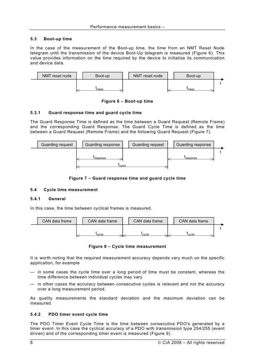
The SYNC Reaction Time is defined as the time between the reception of a SYNC telegram
and the transmission of the "response" PDO (Figure 4).
Figure 4 – SYNC reaction time
5.2.4
SDO response time
The SDO Response Time is defined as the time between the SDO request of a Client SDO
and the SDO response of the Server SDO with expedited transfer (Figure 5).
CiA 2008 – All rights reserved
Figure 5 – SDO response time
7
�
Performance measurement basics –
5.3 Boot-up time
In the case of the measurement of the Boot-up time, the time from an NMT Reset Node
telegram until the transmission of the device Boot-Up telegram is measured (Figure 6). This
value provides information on the time required by the device to initialise its communication
and device data.
5.3.1
Guard response time and guard cycle time
Figure 6 – Boot-up time
The Guard Response Time is defined as the time between a Guard Request (Remote Frame)
and the corresponding Guard Response. The Guard Cycle Time is defined as the time
between a Guard Request (Remote Frame) and the following Guard Request (Figure 7).
Figure 7 – Guard response time and guard cycle time
5.4 Cycle time measurement
5.4.1
General
In this case, the time between cyclical frames is measured.
Figure 8 – Cycle time measurement
It is worth noting that the required measurement accuracy depends very much on the specific
application, for example
— in some cases the cycle time over a long period of time must be constant, whereas the
time difference between individual cycles may vary
— in other cases the accuracy between consecutive cycles is relevant and not the accuracy
over a long measurement period.
As quality measurements the standard deviation and the maximum deviation can be
measured.
5.4.2
PDO timer event cycle time
The PDO Timer Event Cycle Time is the time between consecutive PDO's generated by a
timer event. In this case the cyclical accuracy of a PDO with transmission type 254/255 (event
driven) and of the corresponding timer event is measured (Figure 9).
8
CiA 2008 – All rights reserved
�
