
【资料简介】
【资料截图】


【资料目录】
AD2816 AD2816P AD2816F 现场维修手册 上海震旦办公自动化销售有限公司
【资料截图】
【资料目录】
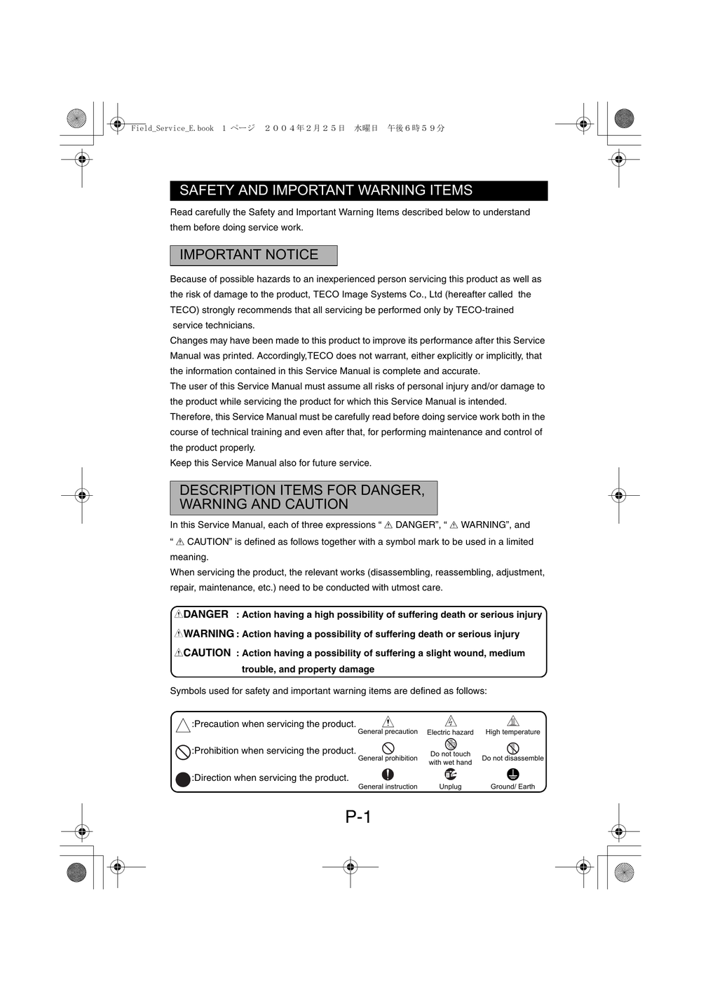
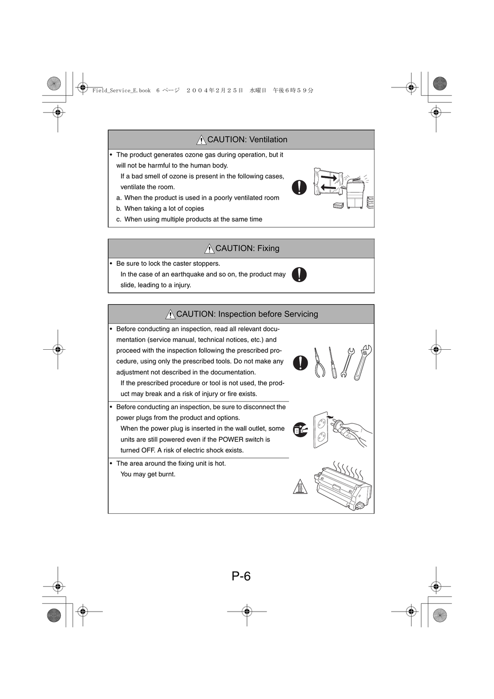
SAFETY AND IMPORTANT WARNING ITEMS
IMPORTANT NOTICE
DESCRIPTION ITEMS FOR DANGER,WARNING AND CAUTION
SAFETY WARNINGS
1. MODIFICATIONS NOT AUTHORIZED BY KONICA MINOLTA BUSINESS TECHNOLOGIES, INC.
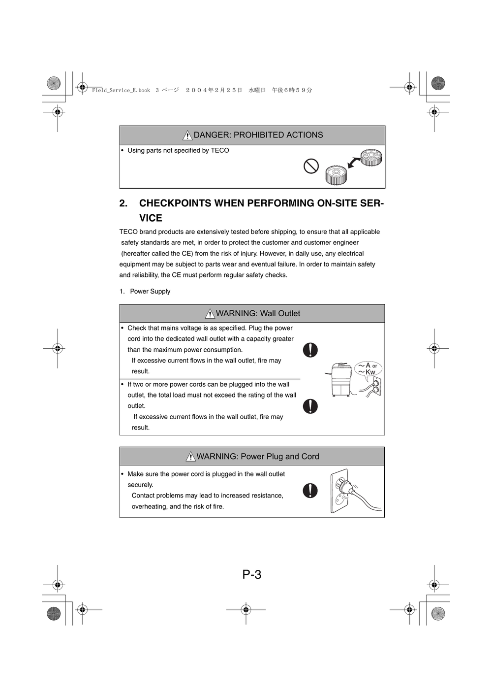
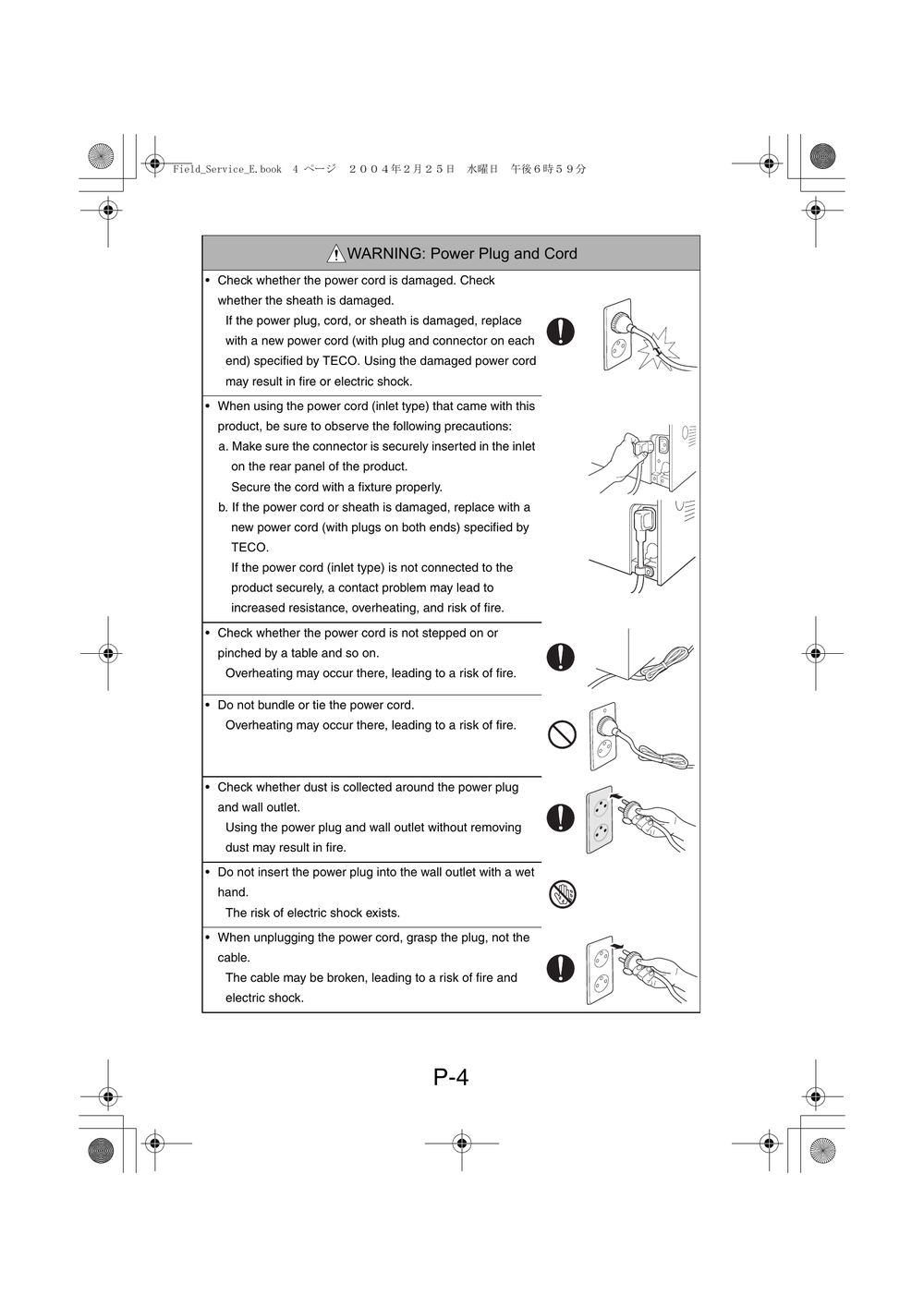
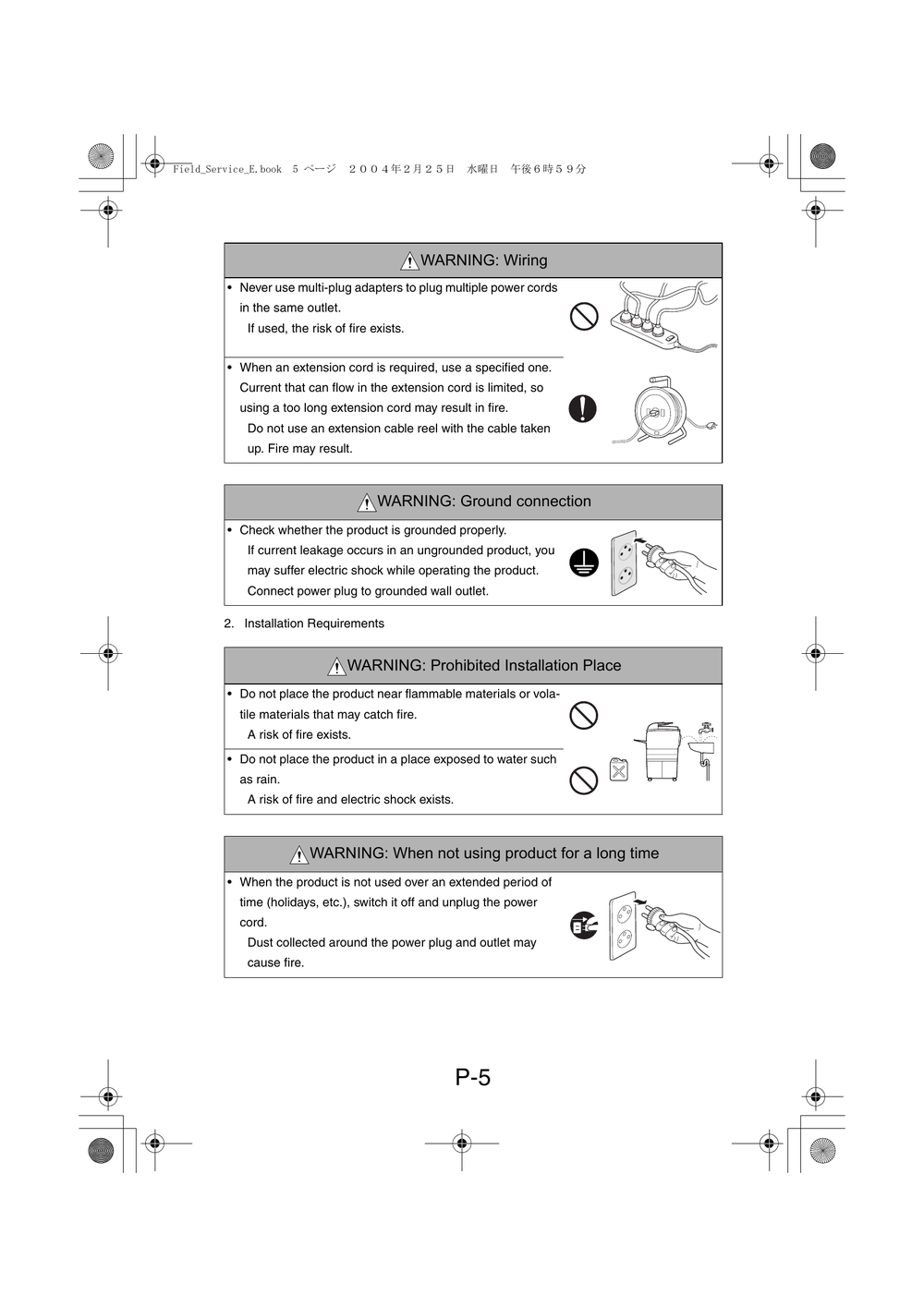
2. CHECKPOINTS WHEN PERFORMING ON-SITE SERVICE
3. MEASURES TO TAKE IN CASE OF AN ACCIDENT
4. CONCLUSION
5. Used Batteries Precautions
CONTENTS
GENERAL
1. SPECIFICATIONS
1-1. Di1610
(1) Main Unit
(2) GDI Printer Function
1-2. Di1610f
(1) Main Unit
(2) GDI Printer Function
(3) FAX Function
2. PRECAUTIONS FOR INSTALLATION
2-1. Installation Site
2-2. Power Source
3. PRECAUTIONS FOR USE
3-1. To Ensure the Printer is Used in an Optimum Condition
3-2. Operating Environment
3-3. Power Requirements
4. HANDLING OF THE CONSUMABLES
5. MISCELLANEOUS PRECAUTIONS
6. PARTS IDENTIFICATION
MAINTENANCE
1. MAINTENANCE SCHEDULE
1-1. Guidelines for Life Specifications Values by Unit
(1) Life Specifications Values
2. REPLACEMENT/CLEANING OF PARTS
(1) Cleaning of the Paper Take-Up Roller
(2) Replacement of the Paper Take-Up Roller
(3) Replacement of the Image Transfer Roller
3. REPLACEMENT OF UNITS
(1) Replacement of the Toner Cartridge
(2) Replacement of the Drum Cartridge
(3) Replacement of the Fusing Unit
DIS/REASSEMBLY, ADJUSTMENT
1. SAFETY INFORMATION
1-1. Laser Safety
1-2. Internal Laser Radiation
1-3. Laser Safety Label
1-4. Laser Caution Label
1-5. Precautions for Handling the Laser Equipment
2. PRECAUTIONS FOR DISASSEMBLY/ADJUSTMENTS
2-1. Parts That Must Not be Touched
(1) Red Painted Screws
(2) Variable resistors on board
(3) Other Screws not Marked with Red Paint
3. DISASSEMBLY/REASSEMBLY
3-1. Identification of Exterior Parts and Removal Procedures for Them
3-2. Removal of Circuit Boards and Other Electrical Components
(1) Removal of the Network Interface Card Board (Option for Di1610f)
(2) Removal of the Network Control Unit Board (Di1610f only)
(3) Removal of the Controller/Mechanical Control Board
(4) Removal of the Control Panel
(5) Removal of the Interface Board
(6) Removal of the Plate NIC Board (Option for Di1610f)
(7) Removal of the Power Unit
(8) Removal of the High Voltage Unit
3-3. Removal of Units
(1) Removal of the IR Unit
(2) Removal of the PH Unit
3-4. Disassembly of the Image Reading Section
(1) Removal of the Original cover set sensor
(2) Removal of the Upper Cover Assy. (Original Glass)
(3) Removal of the Scanner Motor
(4) Removal of the Scanner Assy.
(5) Removal of the Timing Belt
3-5. Disassembly of the Main Drive Section
(1) Removal of the Main Motor
(2) Removal of the Paper Empty Sensors
(3) Removal of the Paper Take-Up Solenoid
(4) Removal of the Paper Take-Up Clutch Gear
(5) Removal of the Torque Limiter
(6) Disassembly of the Fusing Unit
4. ADJUSTMENTS
4-1. Electrical/Image Adjustment
(1) Accessing the Service Mode
(2) Accessing the “ADJUST” Menu
(3) Printing a Test Pattern
(4) Margin Adjustment (Leading Edge/Trailing Edge/Both Sides)
(5) Printer’s Main Scanning Registration Adjustment
(6) Printer’s Sub-Scanning Registration Adjustment
(7) Scanner’s Main Scanning Zoom Ratio Adjustment
(8) Scanner’s Sub-Scanning Zoom Ratio Adjustment
(9) Scanner’s Main Scanning Registration Adjustment
(10) Scanner’s Sub-Scanning Registration Adjustment
4-2. ADJUSTMENT OF JUMPER SWITCHES ON NCU BOARD
5. MISCELLANEOUS
5-1. Removal of the Mechanical Counter (Option)
5-2. Updating the Firmware
(1) Installing the GDI Printer Driver/ TWAIN Driver Using Plug and Play
(2) Procedure for Upgrading the Firmware (Engine firmware/ Copier firmware/ FAX firmware)
5-3. Procedure for Upgrading the FAX Firmware (Upgrading Procedure Using Telephone Line from fax machine to fax machine)
5-4. Remedy for a Failed Updating of the Firmware
5-5. Moving the EEPROM
CONTROL PANEL/SERVICE MODE DESCRIPTIONS
1. CONTROL PANEL DESCRIPTIONS
1-1. Names of Control Panel Parts and Their Functions (Di1610)
1-2. Names of Control Panel Parts and Their Functions (Di1610f)
2. FUNCTIONS OF SWITCHES AND PARTS ON PWBs
2-1. Circuit Board Locations (Di1610)
2-2. Circuit Board Locations (Di1610f)
2-3. PWB-P (Controller/Mechanical Control Board)
2-4. PWB-IF (Interface Board)
2-5. NCU (Network Control Unit Board) (Di1610f only)
2-6. NIC NC-5 (Network Interface Card Board) (Option for Di1610f)
2-7. NIC-IF (Plate NIC Board) (Option for Di1610f)
3. STATUS MODE
3-1. Status Mode Function Tree
3-2. Status Mode Setting Procedure
(1) Total Page
(2) TX/ RX Result (Di1610f only)
(3) Print Report (Di1610f only)
4. UTILITY MODE (Di1610)
4-1. Utility Mode Function Tree
4-2. Utility Mode Setting Procedure
(1) Machine Setting
(2) Paper Source Setting
(3) User management
(4) Copy Setting
5. UTILITY MODE (Di1610f)
5-1. Utility Mode Function Tree (Outline)
5-2. Utility Mode Function Tree (Details)
5-3. Utility Mode Setting Procedure
(1) Machine Setting
(2) Paper source setting
(3) User management
(4) Admin. management
(5) Copy setting
(6) FAX registration
(7) TX operation
(8) RX operation
(9) Comm. setting
(10) Reporting
(11) Initial user data
(12) Network setting
(13) E-mail setting 1
(14) E-mail setting 2
(15) Scan setting
6. SERVICE MODE (Di1610)
6-1. Service Mode Function Tree
6-2. Service Mode Setting Procedure
(1)
(2)
(3)
6-3. Service Mode Functions
(1) Service's Choice
(2) Adjust
(3) Counter
(4) Display
(5) Function
(6) Fixed Zoom Change
(7) Factory Test
(8) Clear Data
7. SERVICE MODE (Di1610f)
7-1. Service Mode Function Tree (Outline)
7-2. Service Mode Function Tree (Details)
7-3. Service Mode Setting Procedure
7-4. Service’s Choice Functions
(1) Marketing Area
(2) Shipment Destination
(3) Leading Edge Erase
(4) Trailing Edge Erase
(5) Vertical Edge Erase
(6) FLS Paper Size
(7) TX Speed
(8) RX Speed
(9) TX Level
(10) RX Level
(11) DTMF Level
(12) CNG Level
(13) CED Level
(14) ECM Mode
(15) Coding Scheme
(16) Toner Empty Report
(17) Protocol Report
(18) GDI Time out
(19) Toner Empty Stop
(20) Pre-rotation
(21) Fuser Temp Ad.
7-5. Adjust Function
(1) Adjust
7-6. Counter Function
(1) Counter
7-7. Display Function
(1) Display
7-8. Function
(1) Function
7-9. Soft Switch Function
7-10. Reporting
(1) Service Data List
(2) Error Code List
(3) T.30 Protocol List
7-11. Admin. Registration (Administrator number registration)
7-12. Fixed zoom change
(1)
(2)
7-13. Factory Test
7-14. Clear Data
(1) DRAM clear
(2) SRAM clear
(3) Memory clear
(4) Total clear
(5) PM counter (clear)
(6) I/C counter (clear)
(7) Application counter (clear)
(8) Scan counter (clear)
(9) Printer JAM counter (clear)
(10) ADF JAM counter (clear)
(11) Trouble counter (clear)
8. Security Mode
8-1. Security Mode Function Tree
8-2. Security Mode Setting Procedure
(1) Security
9. Soft Switch Set (Di1610f only)
9-1. Description
9-2. Default setting
(1) Country for each Marketing area
9-3. Default soft switch setting for each market area 1
9-4. Default soft switch setting for each market area 2
9-5. Default soft switch setting for each market area 3
9-6. Default soft switch setting for each market area 4
9-7. Default soft switch setting for each market area 5
9-8. Default soft switch setting for each market area 6
9-9. Default soft switch setting for each market area 7
9-10. Default soft switch setting for each market area 8
9-11. Soft Switch List
9-12. Soft Switch definition
(1) SOFT SWITCH: #01
(2) SOFT SWITCH: #02
(3) SOFT SWITCH: #03
(4) SOFT SWITCH: #04
(5) SOFT SWITCH: #05
(6) SOFT SWITCH: #06
(7) SOFT SWITCH: #07
(8) SOFT SWITCH: #08
(9) SOFT SWITCH: #09
(10) SOFT SWITCH: #10
(11) SOFT SWITCH: #11
(12) SOFT SWITCH: #12
(13) SOFT SWITCH: #13
(14) SOFT SWITCH: #14
(15) SOFT SWITCH: #15
(16) SOFT SWITCH: #16
(17) SOFT SWITCH: #17
(18) SOFT SWITCH: #18
(19) SOFT SWITCH: #19
(20) SOFT SWITCH: #20
(21) SOFT SWITCH: #21
(22) SOFT SWITCH: #22
(23) SOFT SWITCH: #23
(24) SOFT SWITCH: #24
(25) SOFT SWITCH: #25
(26) SOFT SWITCH: #26
(27) SOFT SWITCH: #27
(28) SOFT SWITCH: #28
(29) SOFT SWITCH: #29
(30) SOFT SWITCH: #30
(31) SOFT SWITCH: #31
(32) SOFT SWITCH: #32
(33) SOFT SWITCH: #33
(34) SOFT SWITCH: #34
(35) SOFT SWITCH: #35
(36) SOFT SWITCH: #36
(37) SOFT SWITCH: #37
(38) SOFT SWITCH: #38
(39) SOFT SWITCH: #39
(40) SOFT SWITCH: #40
(41) SOFT SWITCH: #41
(42) SOFT SWITCH: #42
(43) SOFT SWITCH: #43
(44) SOFT SWITCH: #44
(45) SOFT SWITCH: #45
(46) SOFT SWITCH: #46
(47) SOFT SWITCH: #47
(48) SOFT SWITCH: #48
(49) SOFT SWITCH: #49
(50) SOFT SWITCH: #50
(51) SOFT SWITCH: #51
(52) SOFT SWITCH: #52
(53) SOFT SWITCH: #53
(54) SOFT SWITCH: #54
(55) SOFT SWITCH: #55
(56) SOFT SWITCH: #56
(57) SOFT SWITCH: #57
(58) SOFT SWITCH: #58
(59) SOFT SWITCH: #59 Part 1
(60) SOFT SWITCH: #59 Part 2
(61) SOFT SWITCH: #59 Part 3
(62) SOFT SWITCH: #60
(63) SOFT SWITCH: #61
(64) SOFT SWITCH: #62
(65) SOFT SWITCH: #63
(66) SOFT SWITCH: #64
10. Fax Protocols
10-1. G3 ECM (G3 Error Correction Mode)
10-2. Line Control
(1) Procedure of G3 mode communication
10-3. Table of reference code
10-4. How to analyze the T30 protocol monitor
TROUBLESHOOTING
1. INTRODUCTION
1-1. Electric Components Check Procedures
(1) Sensors
(2) Switches
(3) Solenoids
(4) Motors
1-2. Overall Control Configuration
2. PAPER MISFEED
2-1. Initial Check Items
2-2. Paper Misfeed Displays
2-3. Locations of Misfeed Detection Sensors
2-4. Misfeed Detection Timing and Troubleshooting Procedures
(1) Paper Take-Up/Transport Misfeed
(2) Fusing/Exit Misfeed
3. MALFUNCTIONS/WARNING
3-1. List of Malfunctions
3-2. Malfunction Detection Timing and Troubleshooting Procedures
(1) C0045: Fuser fan motor error
(2) C0210: H.V. abnormal
(3) C0500: Fuser warm up error
(4) C0510: Fuser temperature low
(5) C0520: Fuser overheat
(6) C0650: Scanner home sensor error
(7) C1200: ASIC memory abnormal
(8) C1300: Polygon mirror motor error
(9) C133B: Communication with option error
(10) C133C: Modem error
(11) C133D: ROM checksum error
(12) C13F0: Laser error
(13) C1468: EEPROM error
(14) C14A3: IR lamp malfunction
4. MALFUNCTIONS RELATED TO POWER SUPPLY
4-1. Power is not Turned ON.
5. IMAGE QUALITY PROBLEMS
5-1. Troubleshooting Image Quality Problems
5-2. Initial Checks
5-3. Troubleshooting for Specific Image Quality Problems
(1) Image reading system: Blank or black prints
(2) Image reading system: Low image density
(3) Image reading system: Foggy background or rough image
(4) Image reading system: Black streaks or bands
(5) Image reading system: Black spots
(6) Image reading system: Blank streaks or bands
(7) Image reading system: Uneven image
(8) Printer system: Blank or black prints
(9) Printer system: Blank spots
(10) Printer system: Smears on back
(11) Printer system: Low image density
(12) Printer system: Foggy background
(13) Printer system: Blank streaks or bands
(14) Printer system: Black streaks or bands
(15) Printer system: Offset image
(16) Printer system: Uneven image
6. FAX Error (Di1610f only)
6-1. Communication Error
(1) Outline
(2) Error occurring during transmission
(3) Error occurring during reception
6-2. Error Code
(1) Reception
(2) Transmission
AF-1610
CONTENTS
GENERAL
1. SPECIFICATIONS
DIS/REASSEMBLY, ADJUSTMENT
1. MAINTENANCE SCHEDULE
2. REPLACEMENT/CLEANING OF PARTS
(1) Cleaning of the Paper Take-Up Roll
(2) Replacement of the Paper Take-Up Roll
(3) Cleaning of the Pick-Up Roller
(4) Removal of the Pick-Up Roller
(5) Cleaning of the Registration Rollers
(6) Cleaning of the Transport Roller
(7) Cleaning of the Exit Roller
(8) Cleaning of the Paper Separator Pad
(9) Removal of the Paper Separator Pad
3. DISASSEMBLY/REASSEMBLY
3-1. Names/Removal of External Parts
3-2. Removal of Circuit Boards
(1) Removal of the Automatic Document Feeder Control Board
3-3. Disassembly
(1) Removal of the Automatic Document Feeder Main Motor
4. ADJUSTMENTS
4-1. Electrical/Image Adjustment
(1) Accessing the Service Mode
(2) Accessing the “ADJUST” Menu
(3) Printing a Test Page
(4) Height Adjustment
(5) Leading Edge Tilt Adjustment
(6) Automatic Document Feeder Sub-Scanning Zoom Ratio Adjustment
(7) Automatic Document Feeder Main Scanning Registration Adjustment
(8) Automatic Document Feeder Sub-Scanning Registration Adjustment
TROUBLESHOOTING
1. INTRODUCTION
1-1. Electric Components Check Procedures
(1) Sensors
(2) Clutches
(3) Motors
2. PAPER MISFEED
2-1. Initial Check Items
2-2. Paper Misfeed Displays
2-3. Locations of Misfeed Detection Sensors
2-4. Misfeed Detection Timing and Troubleshooting Procedures
(1) The Original misfeeds
3. TIMING CHART
PF-1610
CONTENTS
GENERAL
1. SPECIFICATIONS
DIS/REASSEMBLY, ADJUSTMENT
1. MAINTENANCE SCHEDULE
2. REPLACEMENT/CLEANING OF PARTS
(1) Cleaning of the Paper Take-Up Roll
(2) Replacement of the Paper Take-Up Roll
3. DISASSEMBLY/REASSEMBLY
3-1. Identification of Exterior Parts and Removal Procedures for Them
3-2. Removal of Circuit Boards
(1) Removal of the Paper Feed Cassette Control Board
3-3. Disassembly
(1) Removal of the Paper Feed Cassette Paper Take-Up Unit
(2) Removal of the Paper Size Detecting Switch
(3) Removal of the Paper Feed Cassette Paper Take-Up Solenoid
NC-1610/IFC-1610
CONTENTS
GENERAL
1. SPECIFICATIONS
DIS/REASSEMBLY, Updating the Firmware
1. Updating the Firmware
2. DISASSEMBLY/REASSEMBLY
(1) Removal of the Network Interface Card
(2) Removal of the Plate NIC Board
(3) Removal of the Internet Fax & Network Scan Kit
TROUBLESHOOTING
1. TROUBLESHOOTING
1-1. Troubleshooting Procedure Overview
1-2. Troubleshooting Procedure Chart
1-3. Main Error Messages and Their Remedies
1-4. Troubleshooting Functions
1-5. List of Communication Error Codes
【资料预览】AD2816 AD2816P AD2816F 现场维修手册 上海震旦办公自动化销售有限公司


