
【资料简介】
【资料截图】

【资料目录】
【资料截图】
【资料目录】
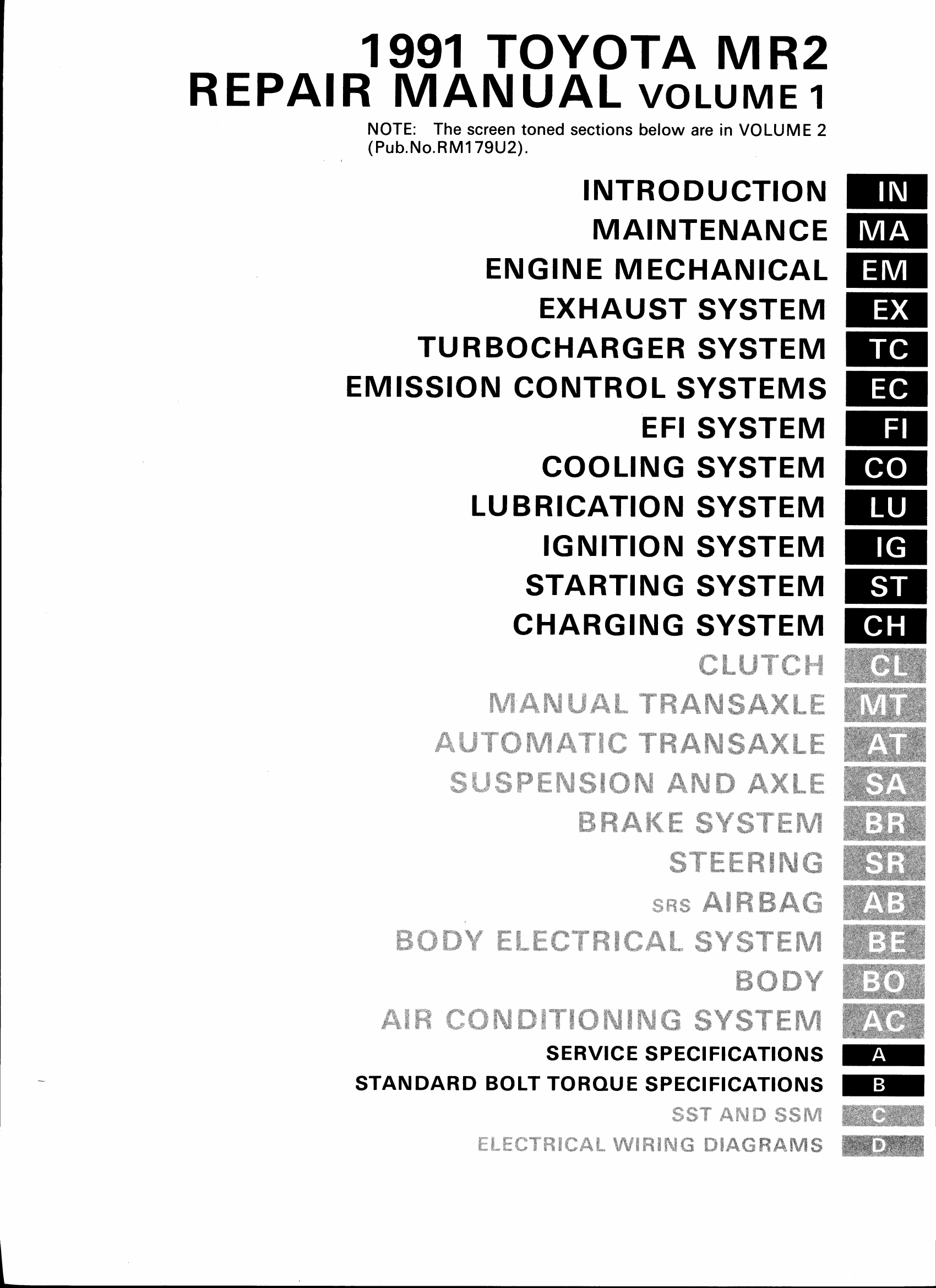
Volume 1.
Contents
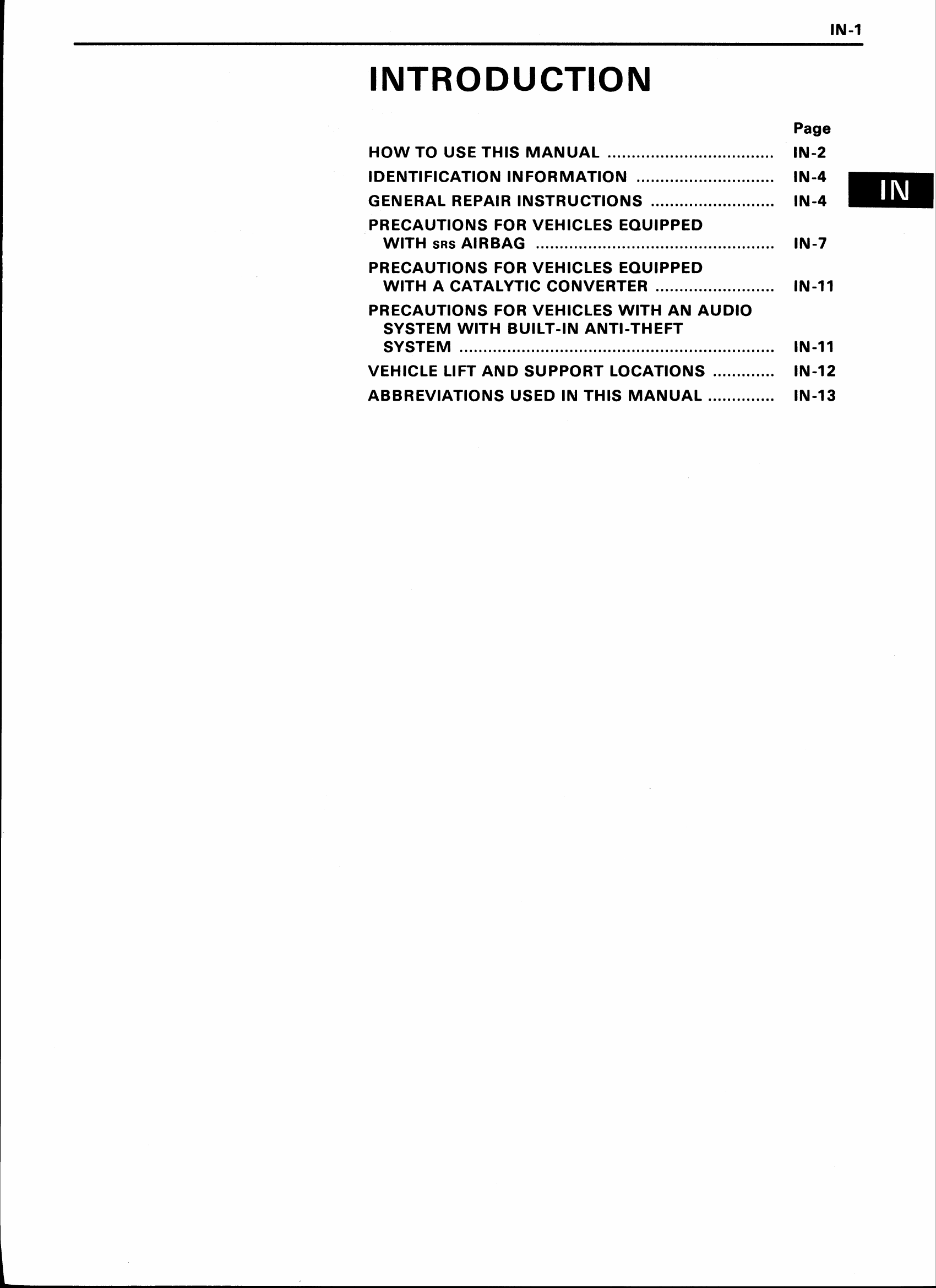
Introduction
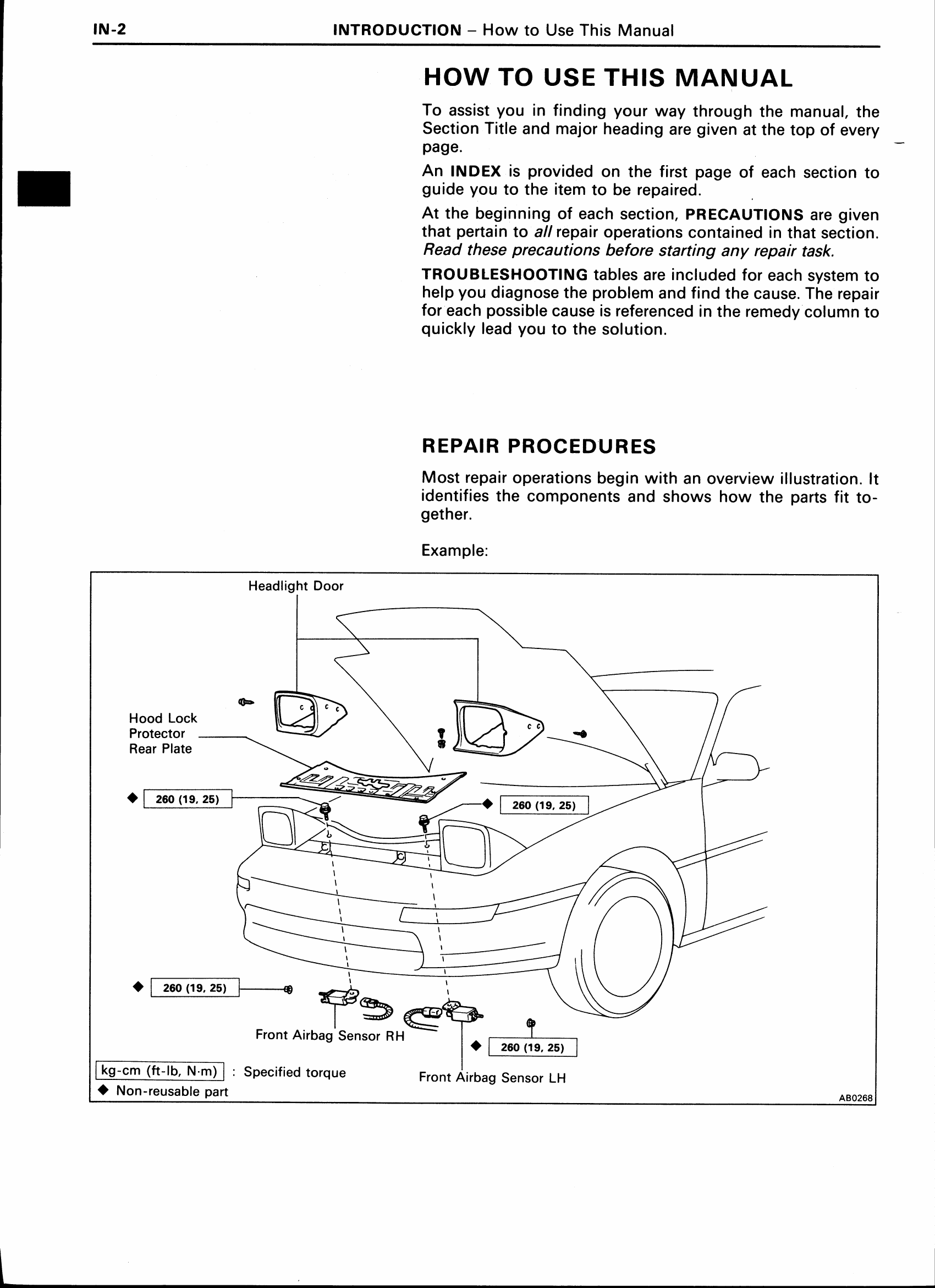
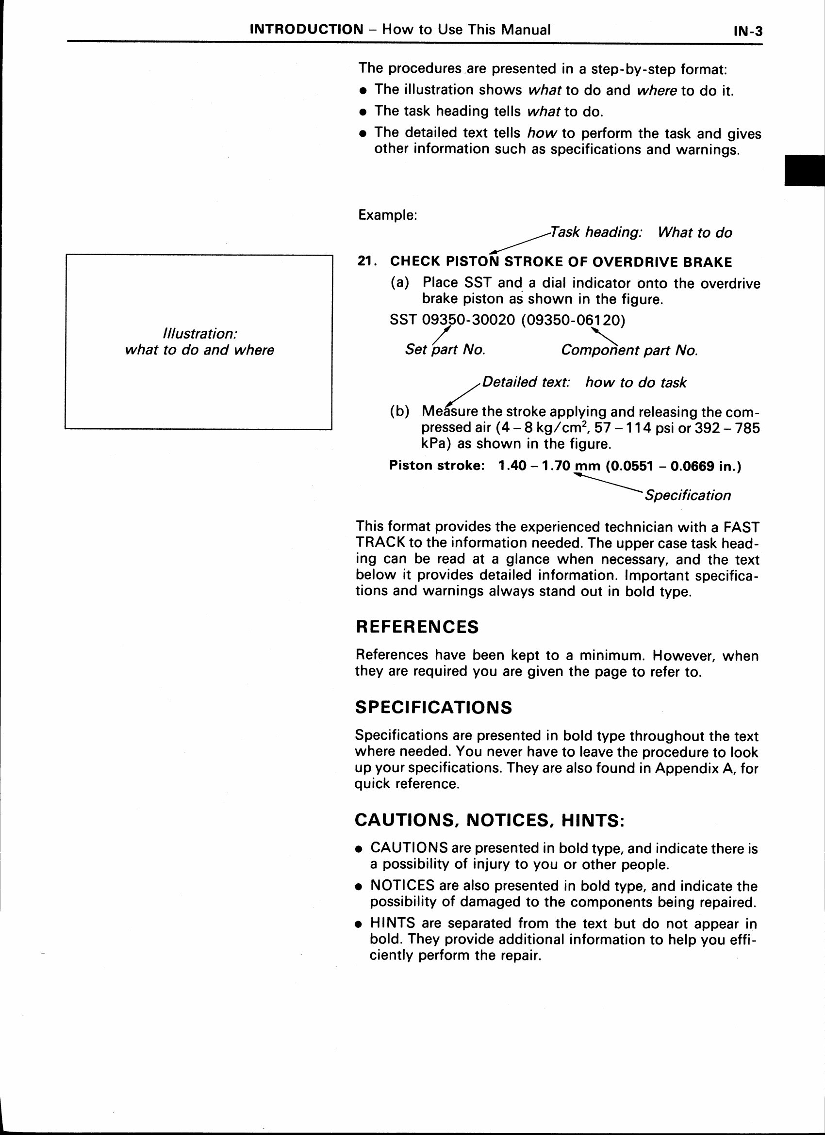
How to use this manual
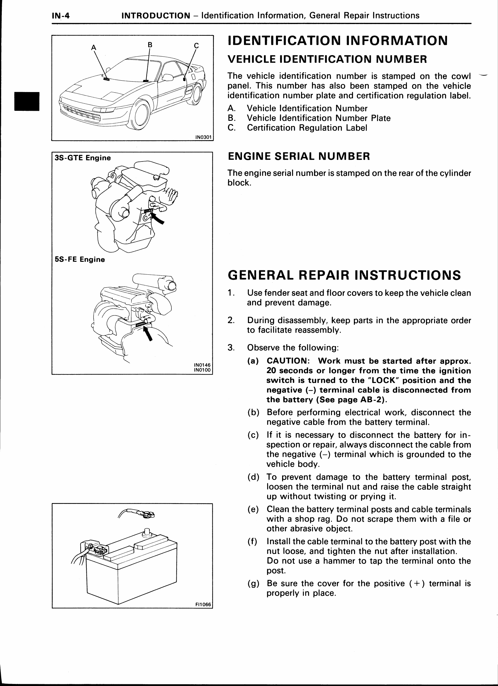
Identification information
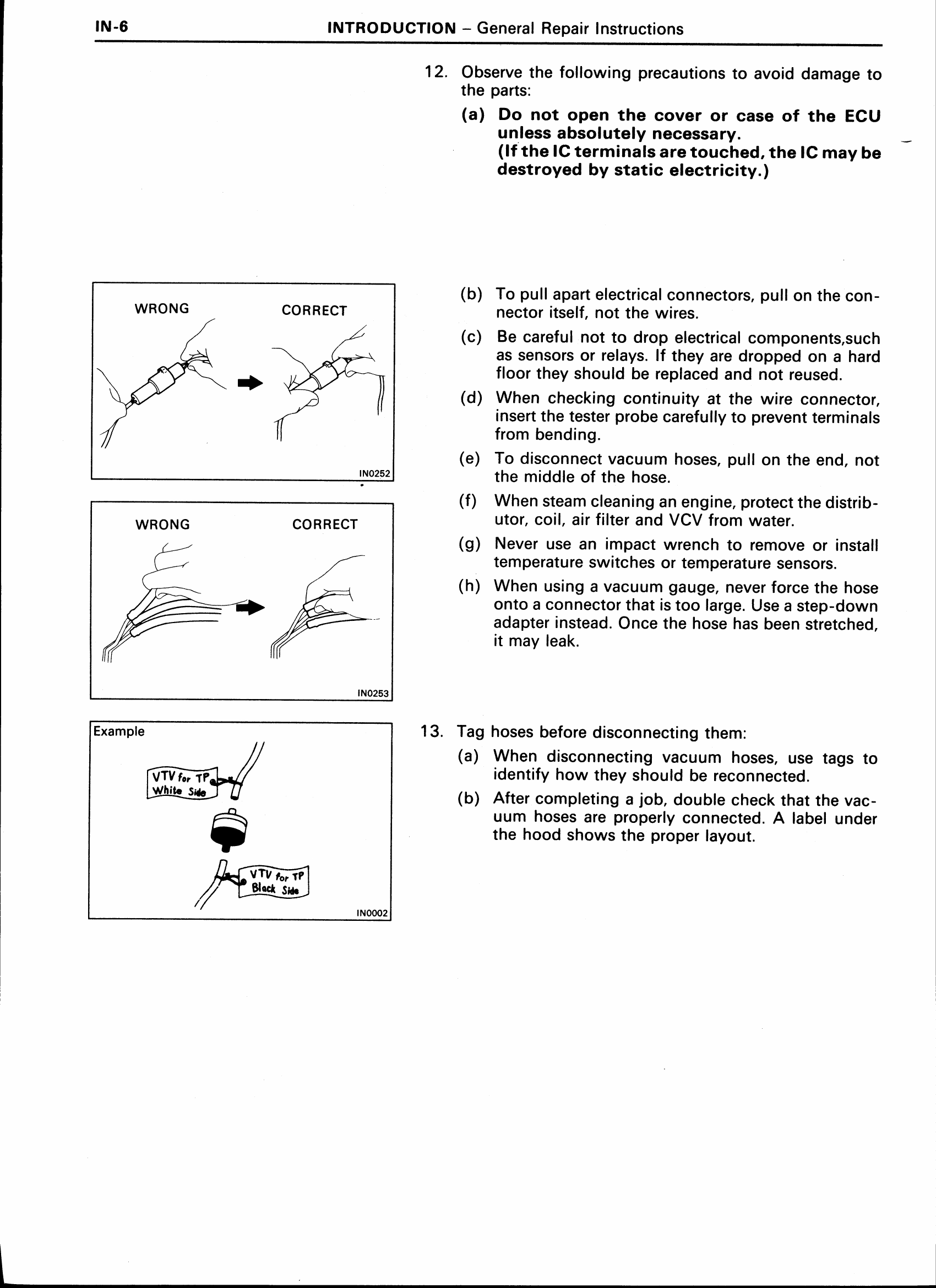
General repair instructions
Precautions for vehicles with Airbag
Precautions for vehicles with catalytic converter
Precautions for vehicles with audio and anti-theft systems
Vehicle lift and support locations
Abbreviations
Maintenance
Maintenance schedule
Maintenance operations
General maintenance
Engine Mechanical
Descritption (3S-GTE)
Description (5S-FE)
Troubleshooting
Engine tune-up
Toyota-variable induction system
Idle and/or 2,500 RPM HC/CO checking
Compression check
Timing belt (3S-GTE)
Timing belt (5S-FE)
Cylinder head (3S-GTE)
Cylinder head (5S-FE)
Cylinder block (3S-GTE)
Cylinder block (5S-FE)
Exhaust System
Exhaust pipes and heat insulators
Turbocharger System
Description
Precautions
Troubleshooting
Turbocharger
Intercooler
Emission Control Systems
3S-GTE
System purpose
Component layout and schematic drawing
Positive crankcase ventilation system
Fuel evaporative emission control system
Exhaust gas recirculation system
Three-way catalyst system
5S-FE
System purpose
Component layout and schematic drawing
Positive crankcase ventilation system
Fuel evaporative emission control system
Exhaust gas recirculation system
Three-way catalyst system
EFI System
Description
Precautions
Inspection precautions
Troubleshooting
Diagnosis system
Troubleshooting with volt/ohmmeter
Fuel System
Fuel pump
Cold start injector (3S-GTE)
Cold start injector (5S-FE)
Fuel pressure regulator (3S-GTE)
Fuel pressure regulator (5S-FE)
Injectors (3S-GTE)
Injectors (5S-FE)
Fuel tank and lines
Air Induction System
Air flow meter (3S-GTE)
Throttle body (3S-GTE)
Throttle body (5S-FE)
Idle speed control valve (3S-GTE)
Idle speed control valve (5S-FE)
Electronic Control System
Location of electronic control parts
EFI main relay
Circuit opening relay
Cold start injector time switch
Solenoid resistor (3S-GTE)
Fuel pump relay and resistor (3S-GTE)
Fuel pressure VSV (5S-FE)
T-VIS VSV (3S-GTE)
Turbocharging pressure VSV (3S-GTE)
EGR VSV
Water temperature sensor
Intake air temperature sensor (5S-FE)
Vacuum sensor (5S-FE)
Turbocharging pressure sensor (3S-GTE)
EGR gas temperature sensor (3S-GTE & 5S-FE Calif. only)
Oxygen sensor (main)
Sub-oxygen sensor (5S-FE Calif. only)
Electronic controlled unit (ECU)
Fuel cut RPM
Cooling System
Description
Troubleshooting
Engine coolant check
Replacement of engine coolant
Water pump
Thermostat
Radiator
Electric cooling fans
Radiator cooling fans (w/ A/C)
Radiator cooling fan (w/o A/C)
Engine compartment cooling fan (3S-GTE)
Lubrication System
Description
Troubleshooting
Oil pressure check
Replacement of engine oil and oil filter
Oil pump
Oil cooler (3S-GTE)
Oil cooler (5S-FE)
Oil Nozzles (3S-GTE)
Ignition System
Precautions
Troubleshooting
Ignition system circuit
On-vehicle inspection (3S-GTE)
On-vehicle inspection (5S-FE)
Distributor (3S-GTE)
Distributor (5S-FE)
Starting System
Troubleshooting
Starter
Starter relay
Clutch start switch (M/T only)
Charging System
Precautions
Troubleshooting
On-vehicle inspection
Alternator
Ignition main relay
Service Specification
Maintenance
Engine Mechanical (3S-GTE)
Engine mechanical (5S-FE)
Exhaust system
Turbocharger system
EFI system (3S-GTE)
EFI system (5S-FE)
Cooling system
Lubrication system
Ignition system
Starting system
Charging system
Lubricant
Standard Bolt Torque Specifications
Standard Bolt Torque Specifications
Volume 2.
Contents
Clutch
Troubleshooting
Check and adjustment of clutch pedal
Bleeding of clutch system
Inspection of clutch start system
Clutch master cylinder
Clutch release cylinder
Clutch unit
Manual Transaxle
Description
Precautions
Troubleshooting
Removal and installation of transaxle
S54 Transaxle / SW21 series
Removal of component parts
Component parts
Input shaft assembly
Output shaft assembly
Shift and select lever assembly
Differential
Installation of component parts
E153 Transaxle / SW20 series
Removal of component parts
Component parts
Input shaft assembly
Output shaft assembly
Oil pump
Shift and select lever shaft
Differential
Installation of component parts
Shift lever and control cable
Automatic Transaxle (A241E)
Description
Operation
Troubleshooting
Basic Troubleshooting
Genaral troubleshooting
Preliminary check
Diagnosis system
Electronic control system
Mechanical system tests
Road test
Automatic shift schedule
On-vehicle repair
Removal and installation of transaxle
Torque converter
Removal of component parts
Component parts
General notes
Second coast brake
Oil pump
Direct clutch
Forward clutch
Front planetary gear
Second brake
Rear planetary gear
First and reverse brake
Intermediate shaft
Counter shaft
Underdrive clutch and one-way clutch no. 3
Underdrive brake and B4 accumulator piston
Valve body
Differential
Installation of component parts
Shift lock system
Suspension and Axle
Troubleshooting
Wheel alignment
Front wheel alignment
Rear wheel alignment
Front axle hub
Front suspension
Front shock absorber
Ball joints, lower arm and stabilizer bar
Rear axle shaft and carrier
Rear drive shaft (5S-FE engine)
Rear drive shaft (3S-GTE engine)
Rear suspension
Rear shock absorber
Ball joint, lower arm and stabilizer bar
Engine lateral control rod
Brake System
Precautions
Troubleshooting
Checks and adjustments
Master cylinder
Brake booster
Front brake
PE36T disc (for 3S-GTE)
PD51 disc (for 5S-FE)
Rear brake
Proportioning and by-pass valve
Anti-lock brake system
Description
Diagnosis system
Troubleshooting
Speed sensor diagnosis system
ABS actuator
Control relays
Front speed sensor
Rear speed sensor
Anti-lock brake system circuit
Steering
Precautions
Troubleshooting
On-vehicle inspection
Steering column
Manual steering gear housing
Power steering
Description
On-vehicle inspection
Power steering pump
Gear housing
Electronic control system
Diagnosis system
Inspection of electronic control components
SRS Airbag
General description
Description
Operation
Inspection items and replacement requirements
Removal and installation of component parts
Steering wheel pad and spiral cable
Front airbag Sensor
Center airbag sensor assembly
Replacement of repair wire for front airbag sensor
Troubleshooting
Disposal of steering wheel pad (with airbag)
Disposal of center airbag sensor assembly
Body Electrical System
General information
Power source
Ignition switch
Lighting system
Wiper and washer system
Combination meter
Defogger system
Power window control system
Power door lock control system
Power mirror control system
Cruise control system
Theft deterrent system
Audio
Clock
Body
General information
Hood
Front Hood
Engine Hood
Headlight
Front door
Luggage compartment door
Mouldings
Windshield moulding
Body outside moulding
Side protection moulding
Back window moulding
Windshield
Quarter window glass
Back window glass
T-bar roof
Moon roof
Instrument panel
Seat
Seat belts
Body dimensions
Air Conditioning System
General information
Description
Preparation
Troubleshooting
Refrigeration system
Drive belt
Refrigeration lines
Compressor
Receiver
Condenser
Cooling unit
Evaporator
Expansion valve
Thermistor
A/C control assembly
Pressure switch
Water temperature sensor
Servomotors
Blower motor
Condenser fan motor
Heater main relay
Magnetic clutch relay
Fan main relays
Vacuum hose circuit
Vacuum switching valve
A/C amplifier
Service Specifications
Clutch
Manual transaxle (S54)
Manual transaxle (E153)
Automatic transaxle (A241E)
Suspension and axle
Brake system
Steering
SRS Airbag
Body
Lubricant
Standard Bolt Torque Specifications
Standard Bolt Torque Specifications
Special Service Tools and Materials
Special service tools
Special service materials
【资料预览】


