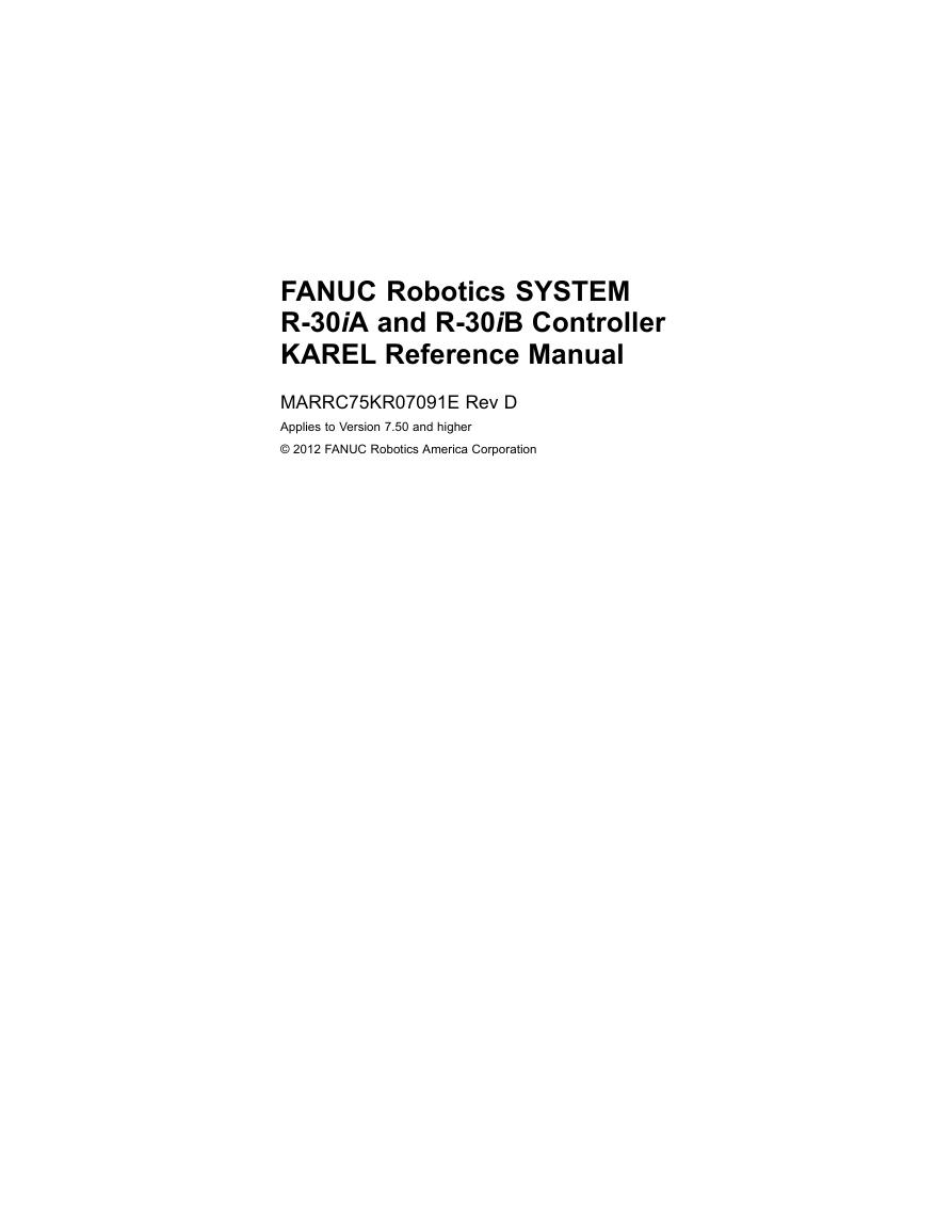
TOSHIBA Photocoupler GaAs Ired & Photo−Transistor
TLP521−1,TLP521−2,TLP521−4
TLP521−1,TLP521−2,TLP521−4
Unit in mm
Programmable Controllers
AC/DC−Input Module
Solid State Relay
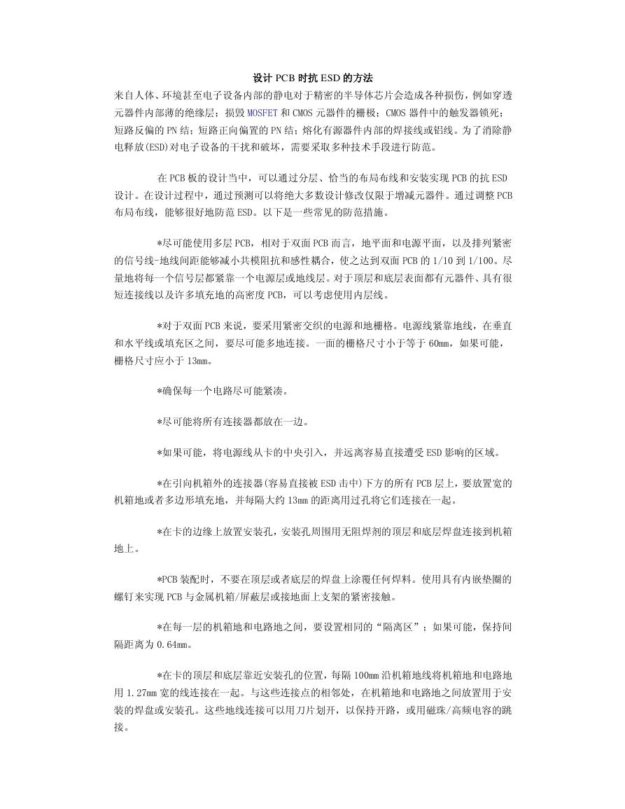
The TOSHIBA TLP521−1, −2 and −4 consist of a photo−transistor
optically coupled to a gallium arsenide infrared emitting diode.
The TLP521−2 offers two isolated channels in an eight lead plastic DIP
package, while the TLP521−4 provides four isolated channels in a
sixteen plastic DIP package.
• Collector−emitter voltage: 55 V (min)
• Current transfer ratio: 50% (min)
Rank GB: 100% (min)
Isolation voltage: 2500 Vrms (min)
•
• UL recognized
made in Japan: UL1577, file No. E67349
made in Thailand: UL1577, file No. E152349
Pin Configurations (top view)
TLP521-1
TLP521-2
TLP521-4
1
2
1 : Anode
2 : Cathode
3 : Emitter
4 : Collector
4
3
1
2
3
4
1, 3 : Anode
2, 4 : Cathode
5, 7 : Emitter
6, 8 : Collector
8
7
6
5
1
2
3
4
5
6
7
8
16
15
14
13
12
11
10
9
TOSHIBA
Weight: 0.26 g
11−5B2
TOSHIBA
Weight: 0.54 g
11−10C4
1, 3, 5, 7
2, 4, 6, 8
9, 11, 13, 15
10, 12, 14, 16
: Anode
: Cathode
: Emitter
: Collector
TOSHIBA
Weight: 1.1 g
11−20A3
1
2007-10-01
�
Absolute Maximum Ratings (Ta = 25°C)
TLP521−1,TLP521−2,TLP521−4
Characteristic
t
e
D
r
o
t
c
e
D
E
L
Forward current
Forward current derating
Pulse forward current
Reverse voltage
Junction temperature
Collector−emitter voltage
Emitter−collector voltage
Collector current
Collector power dissipation
(1 circuit)
Collector power dissipation
derating (1 circuit Ta ≥ 25°C)
Junction temperature
Storage temperature range
Operating temperature range
Lead soldering temperature
Total package power dissipation
Total package power dissipation
derating (Ta ≥ 25°C)
Isolation voltage
Symbol
IF
ΔIF /°C
IFP
VR
Tj
VCEO
VECO
IC
PC
ΔPC /°C
Tj
Tstg
Topr
Tsol
PT
ΔPT /°C
BVS
Rating
TLP521−1
70
TLP521−2
TLP521−4
50
Unit
mA
−0.93 (Ta ≥ 50°C)
−0.5 (Ta ≥ 25°C)
mA /°C
1 (100μ pulse, 100pps)
5
125
55
7
50
125
−55~125
−55~100
260 (10 s)
150
−1.5
250
−2.5
100
−1.0
150
−1.5
A
V
°C
V
V
mA
mW
mW /°C
°C
°C
°C
°C
mW
mW /°C
2500 (AC, 1min., R.H.≤ 60%)
(Note 1)
Vrms
Note: Using continuously under heavy loads (e.g. the application of high temperature/current/voltage and the
significant change in temperature, etc.) may cause this product to decrease in the reliability significantly even
if the operating conditions (i.e. operating temperature/current/voltage, etc.) are within the absolute maximum
ratings.
Please design the appropriate reliability upon reviewing the Toshiba Semiconductor Reliability Handbook
(“Handling Precautions”/“Derating Concept and Methods”) and individual reliability data (i.e. reliability test
report and estimated failure rate, etc).
Note 1: Device considered a two terminal device: LED side pins shorted together and detector side pins shorted
together.
Recommended Operating Conditions
Characteristic
Symbol
Supply voltage
Forward current
Collector current
Operating temperature
VCC
IF
IC
Topr
Min
―
―
―
−25
Typ.
Max
Unit
5
16
1
―
24
25
10
85
V
mA
mA
°C
Note: Recommended operating conditions are given as a design guideline to obtain expected performance of the
device. Additionally, each item is an independent guideline respectively. In developing designs using this
product, please confirm specified characteristics shown in this document.
2
2007-10-01
�
Type
Classi−
fication (*1)
A
Rank Y
Rank GR
Rank BL
Rank GB
A
Rank GB
TLP521
TLP521−2
TLP521−4
Current Transfer Ratio (%)
(IC / IF)
IF = 5mA, VCE = 5V, Ta = 25°C
Min
50
50
100
200
100
50
100
Max
600
150
300
600
600
600
600
TLP521−1,TLP521−2,TLP521−4
Marking Of
Classification
Blank, Y, Y■, G, G■, B, B■, GB
Y, Y■
G, G■
B, B■
G, G■, B, B■, GB
Blank, GR, BL, GB
GR, BL, GB
*1: Ex. rank GB: TLP521−1 (GB)
(Note): Application type name for certification test, please use standard product type name, i.e.
TLP521−1 (GB): TLP521−1, TLP521−2 (GB): TLP521−2
3
2007-10-01
�
Individual Electrical Characteristics (Ta = 25°C)
Characteristic
Symbol
Test Condition
Min
Typ.
Max
Unit
TLP521−1,TLP521−2,TLP521−4
Forward voltage
Reverse current
Capacitance
Collector−emitter
breakdown voltage
Emitter−collector
breakdown voltage
Collector dark current
D
E
L
r
o
t
c
e
t
e
D
Capacitance
(collector to emitter)
VF
IR
CT
IF = 10 mA
VR = 5 V
V = 0, f = 1 MHz
V(BR) CEO
IC = 0.5 mA
V(BR) ECO
IE = 0.1 mA
ICEO
CCE
VCE = 24 V
VCE = 24 V, Ta = 85°C
V = 0, f = 1 MHz
Coupled Electrical Characteristics (Ta = 25°C)
Characteristic
Symbol
Test Condition
Current transfer ratio
Saturated CTR
Collector−emitter
saturation voltage
IC / IF
IF = 5 mA, VCE = 5 V
Rank GB
IC / IF (sat)
IF = 1 mA, VCE = 0.4 V
Rank GB
VCE (sat)
IC = 2.4 mA, IF = 8 mA
IC = 0.2 mA, IF = 1 mA
Rank GB
Isolation Characteristics (Ta = 25°C)
1.0
1.15
1.3
—
30
—
—
10
2
10
10
—
—
—
100
50
—
V
μA
pF
V
V
nA
μA
pF
Typ.
Max
Unit
—
—
60
—
—
0.2
—
600
600
—
—
0.4
—
0.4
%
%
V
—
—
55
7
—
—
—
MIn
50
100
—
30
—
—
—
Characteristic
Symbol
Test Condition
Min
Typ.
Max
Unit
Capacitance
(input to output)
Isolation resistance
Isolation voltage
CS
RS
BVS
VS = 0, f = 1 MHz
VS = 500 V, R.H.≤ 60%
AC, 1 minute
AC, 1 second, in oil
DC, 1 minute, in oil
—
0.8
—
2500
—
—
1011
—
5000
5000
—
—
—
—
—
pF
Ω
Vrms
Vdc
4
2007-10-01
�
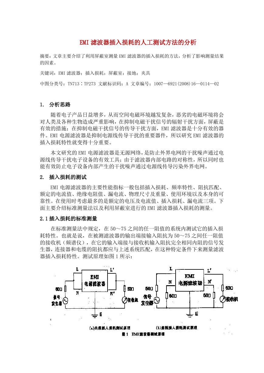
Switching Characteristics (Ta = 25°C)
Characteristic
Symbol
Test Condition
Min
Typ.
Max
Unit
TLP521−1,TLP521−2,TLP521−4
Rise time
Fall time
Turn−on time
Turn−off time
Turn−on time
Storage time
Turn−off time
tr
tf
ton
toff
tON
ts
tOFF
VCC = 10 V
IC = 2 mA
RL = 100Ω
RL = 1.9 kΩ (Fig.1)
VCC = 5 V, IF = 16 mA
—
—
—
—
—
—
—
2
3
3
3
2
15
25
—
—
—
—
—
—
—
μs
μs
Fig.1 : SWITCHING TIME TEST CIRCUIT
IF
RL
VCC
VCE
IF
VCE
tON
tS
VCC
4.5V
0.5V
tOFF
5
2007-10-01
�
t
n
e
r
r
u
c
d
r
a
w
r
o
f
l
e
b
a
w
o
l
l
A
)
A
m
(
F
I
r
e
w
o
p
r
o
t
c
e
l
l
l
o
c
e
b
a
w
o
l
l
A
)
W
m
(
C
P
n
o
i
t
i
a
p
s
s
d
i
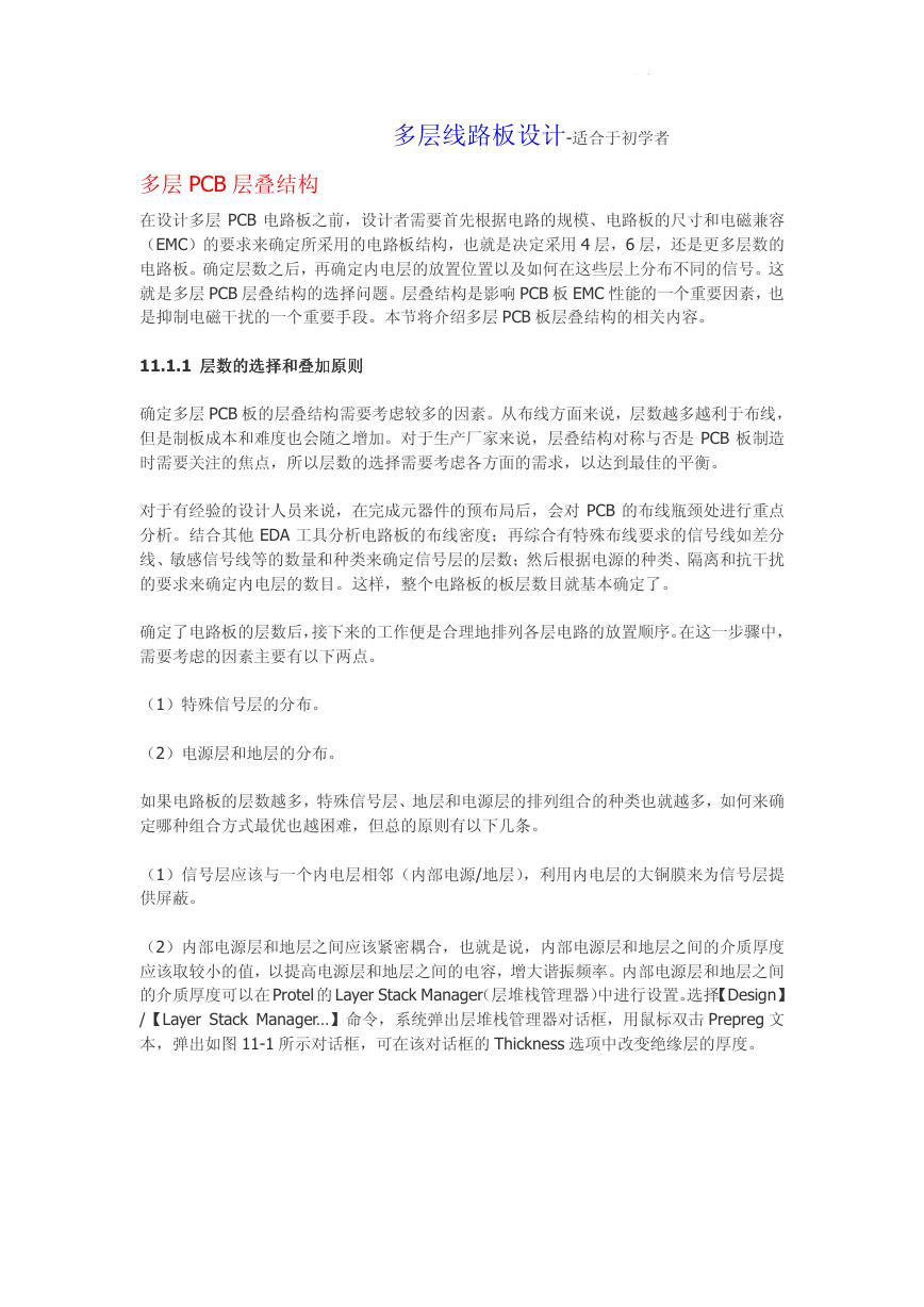
TLP521−1,TLP521−2,TLP521−4
TLP521-1
100
IF – Ta
TLP521-2
TLP521-4
100
IF – Ta
80
60
40
20
0
-20
t
n
e
r
r
u
c
d
r
a
w
r
o
f
l
e
b
a
w
o
)
A
m
(
F
I
l
l
A
0
20
40
60
80
100
Ambient temperature Ta (°C)
TLP521-1
PC – Ta
240
200
160
120
80
40
0
-20
0
20
40
60
80
100
Ambient temperature Ta (°C)
r
e
w
o
p
r
o
t
c
e
l
l
l
o
c
e
b
a
w
o
l
l
A
)
W
m
(
C
P
n
o
i
t
i
a
p
s
s
d
i
80
60
40
20
0
-20
0
20
40
60
80
100
Ambient temperature Ta (°C)
TLP521-2
TLP521-4
PC – Ta
120
100
80
60
40
20
0
-20
0
20
40
60
80
100
Ambient temperature Ta (°C)
d
r
a
w
r
o
f
l
e
s
u
p
e
b
a
w
o
l
l
l
A
)
A
m
(
P
F
I
t
n
e
r
r
u
c
TLP521-1
3000
IFP – DR
Pulse width ≤ 100μs
Ta = 25°C
TLP521-2
TLP521-4
3000
IFP – DR
Pulse width ≤ 100μs
Ta = 25°C
1000
500
300
100
50
30
10
3
d
r
a
w
r
o
f
l
e
s
u
p
e
b
a
w
o
l
l
l
)
A
m
(
P
F
I
t
n
e
r
r
u
c
A
10-3
3
10-2
3
10-1
3
100
Duty cycle ratio DR
1000
500
300
100
50
30
10
3
10-3
3
10-2
3
10-1
3
100
Duty cycle ratio DR
6
2007-10-01
�
)
A
m
(
F
I
t
n
e
r
r
u
c
d
r
a
w
r
o
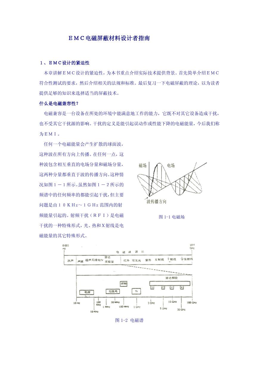
F
IF – VF
Ta=25°C
100
50
30
10
5
3
1
0.5
0.3
TLP521−1,TLP521−2,TLP521−4
ΔVF/ΔTa – IF
-2.8
-2.4
-2.0
-1.6
-1.2
-0.8
)
C
°
/
V
m
(
t
e
r
u
a
r
e
p
m
e
t
e
g
a
t
l
o
v
d
r
a
w
r
o
F
/
a
T
Δ
F
V
Δ
t
i
n
e
c
i
f
f
e
o
c
0.1
0.4
0.6
0.8
1.0
1.2
1.4
1.6
-0.4
0.1
0.3
)
A
m
(
P
F
I
t
n
e
r
r
u
c
d
r
a
w
r
o
f
l
e
s
u
P
)
A
m
(
C
I
t
n
e
r
r
u
c
r
o
t
c
e
l
l
o
C
Forward voltage VF (V)
IFP – VFP
Pulse width ≤10μs
Repetitive frequency =100Hz
Ta = 25°C
0.4
0.8
1.2
1.6
2.0
2.4
Pulse forward voltage VFP (V)
IC – VCE
Ta=25°C
50mA
30mA
20mA
15mA
10mA
PC(MAX.)
IF=5mA
4
2
8
Collector-emitter voltage VCE (V)
6
10
1000
500
300
100
50
30
10
5
3
1
0
80
60
40
20
0
0
1
10
Forward current IF (mA)
3
30
)
A
μ
(
O
E
C
I
t
n
e
r
r
u
c
k
r
a
d
r
o
t
c
e
l
l
o
C
)
A
m
(
C
I
t
n
e
r
r
u
c
r
o
t
c
e
l
l
o
C
101
100
10-1
10-2
10-3
10-4
0
25
20
15
10
5
0
0
ICEO – Ta
10V
5V
VCE=24V
40
80
120
160
Ambient temperature Ta (℃)
IC – VCE
50mA
Ta=25°C
40mA
30mA
20mA
10mA
5mA
IF=2mA
0.2
0.4
0.6
0.8
1.0
1.2
1.4
Collector-emitter voltage VCE (V)
7
2007-10-01
�
)
A
m
(
C
I
t
n
e
r
r
u
c
r
o
t
c
e
l
l
o
C
)
A
m
(
C
I
t
n
e
r
r
u
c
r
o
t
c
e
l
l
o
C
IC – IF
Ta = 25°C
VCE=5V
VCE=0.4V
Sample A
Sample B
100
50
30
10
5
3
1
0.5
0.3
0.1
0.05
0.03
0.3
100
50
30
10
5
3
1
0.5
0.3
0.1
-20
1
3
10
30
100
Forward current IF (mA)
VCE = 5V
IC – Ta
25mA
10mA
5mA
1mA
IF = 0.5mA
20
0
Ambient temperature Ta (℃)
60
40
80
100
TLP521−1,TLP521−2,TLP521−4
IC/IF – IF
Sample A
Sample B
Ta = 25°C
VCE=5V
VCE=0.4V
1
3
10
30
100
Forward current IF (mA)
VCE(sat) – Ta
IF = 5mA
IC = 1mA
500
300
100
50
30
10
5
0.3
0.20
0.16
0.12
0.08
0.04
0
-20
20
0
Ambient temperature Ta (℃)
60
40
80
100
o
i
t
a
r
r
e
f
s
n
a
r
t
t
n
e
r
r
u
C
)
%
(
F
I
/
C
I
n
o
i
t
t
a
r
u
a
s
r
e
t
t
i
m
e
-
r
o
t
c
e
l
l
o
C
)
V
(
)
t
a
s
(
E
C
V
e
g
a
t
l
o
v
)
s
μ
(
e
m
i
t
i
g
n
h
c
t
i
w
S
1000
500
300
100
50
30
10
5
3
1
1
RL – Switching Time
Ta = 25°C
IF = 16mA
VCC= 5V
tOFF
tS
tON
3
10
30
100
300
Load resistance RL (kΩ)
8
2007-10-01
�


 V2版本原理图(Capacitive-Fingerprint-Reader-Schematic_V2).pdf
 摄像头工作原理.doc
 VL53L0X简要说明(En.FLVL53L00216).pdf
 原理图(DVK720-Schematic).pdf
 原理图(Pico-Clock-Green-Schdoc).pdf
 原理图(RS485-CAN-HAT-B-schematic).pdf
 File:SIM7500_SIM7600_SIM7800 Series_SSL_Application Note_V2.00.pdf
 ADS1263(Ads1262).pdf
 原理图(Open429Z-D-Schematic).pdf
 用户手册(Capacitive_Fingerprint_Reader_User_Manual_CN).pdf
 CY7C68013A(英文版)(CY7C68013A).pdf
 TechnicalReference_Dem.pdf